


Vista Solo 1-4 0150-0267A
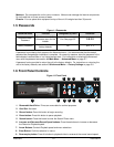
RS-232 Serial Port
Use a Null Modem cable when connecting to a
PC. When connecting to a multiplexer, it may
be necessary to construct a cable using the pin-
out documentation of the MUX as a guide. See
the pin-out configuration for the Vista Solo
below.
Connector Type: DB-9
Gender (on unit): Male
Cable Required (Connected to PC): Null Modem
Cable Required (Connected to Multiplexer):
Variable, depending on pin-out configuration of
MUX.
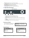
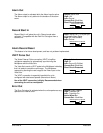
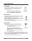
DB-9 Pin Configuration for Serial Port
Pin Use
Pin Use
Pin Use
1 DCD 4 Not Connected 7 RTS
2 RX 5 Ground 8 CTS
3 TX 6 Not Connected 9 Not Connected
RS-232
1
5
6
9
DB-9 Connector on
Back Panel
1.8 Accessories I/O Port
The back panel of the unit is equipped with an Accessories Port (DB-9 style connector) for
connecting peripheral devices such as alarm devices, alarm relays, or the VEXT connection.
Do not attempt to wire accessories directly to the DB-9 connector.
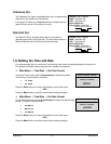
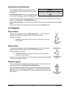
Pin Use
Pin Use
Pin Use
1 Alarm In 4
Alarm Record
Reset
7 Ground
2 Alarm Out 5
VEXT Pulse
Out
8 Videoloss Out
3
Record
Start In
6 Error Out 9 Disk End Out
I/O
1
5
6
9
DB-9 Connector on
Back Panel
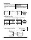
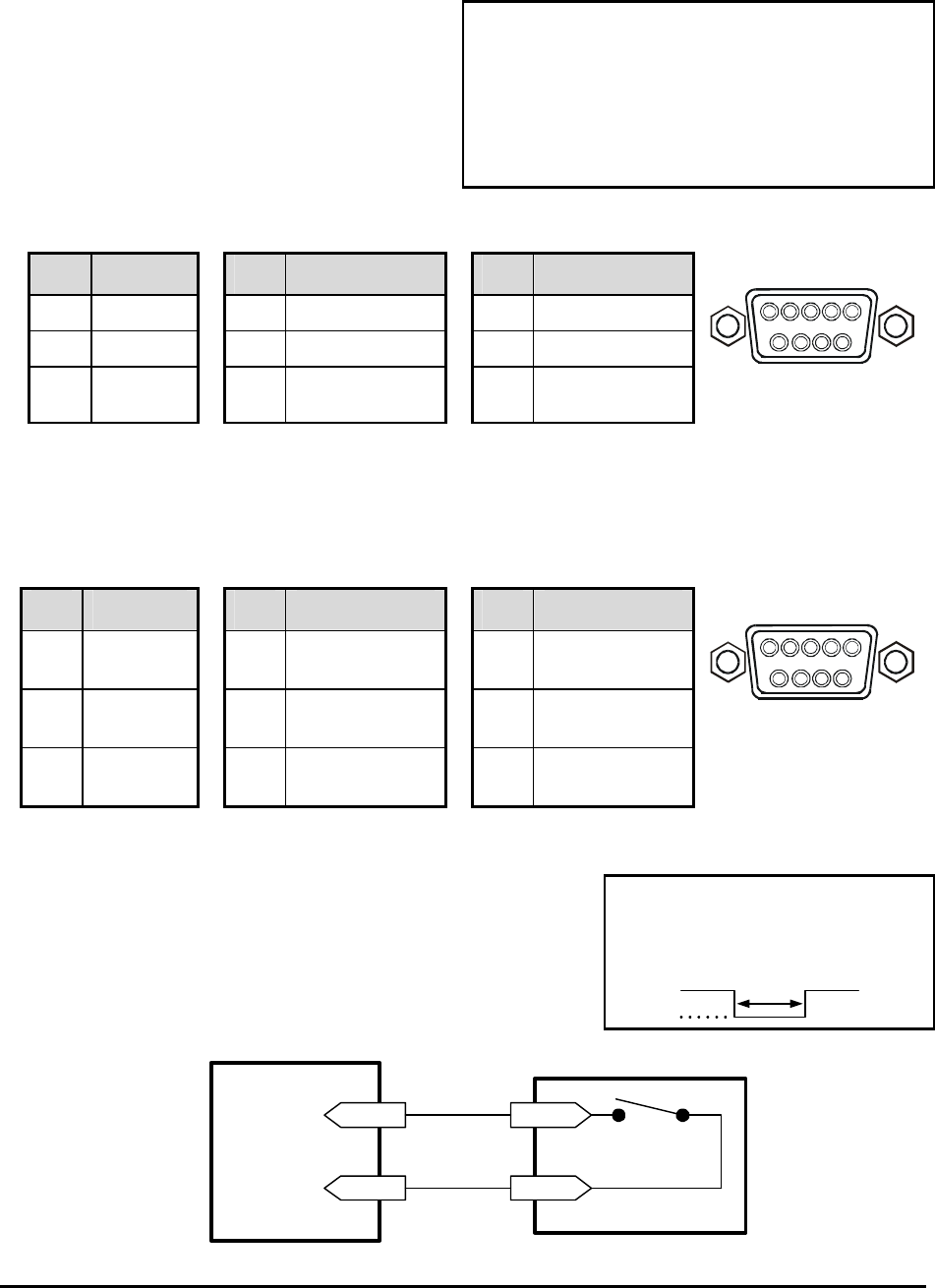
Alarm In
An alarm condition can be activated by an Active Low TTL input
or by relay contact devices such as pressure pads, passive
infrareds, door switches, or other similar devices.
Input: Active Low TTL w/ pull-ups
or Normally Open Relay.
High: 5V (12V tolerant)
Low: Ground
Minimum Duration: 0.5 Seconds
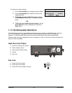
Figure 1-4 Normally Open Relay Alarm Connection
Pin 1
Pin 7 or 10
Alarm Input
Ground
Accessories PCB
Typical Alarm Device
Refer to each alarm devices's
manual for specific wiring details.
Normally Open
(Closes During Alarm)