WHITE-RODGERS
FAILURE TO READ AND FOLLOW ALL INSTRUCTIONS CAREFULLY BEFORE
INSTALLING OR OPERATING THIS CONTROL COULD CAUSE PERSONAL INJURY
AND/OR PROPERTY DAMAGE.
Model No. Voltage
36C21U
36C21
36C21A
Current
D.C.
.23 Amp
.035 Amp
750 MV
24 volts
120 volts
WHITE-RODGERS DIVISION
EMERSON ELECTRIC CO.
9797 REAVIS ROAD
ST. LOUIS, MISSOURI 63123-5398
Printed in U.S.A.
PART NO. 37-4048B
Replaces 37-4048, 37-2570, 37-1972
9615
36C21 Series
Main Gas Valves
INSTALLATION INSTRUCTIONS
Operator: Save these instructions for future use!
These Gas Valves control the flow of gas to the main
burner under command of a room thermostat. They are
suitable for use on all gases and may be used with all
types of gas heating equipment. They may be mounted in
any position except upside down.
Some parts of this gas valve are also used to make more
complex combination gas controls. Disregard the nota-
tions “Pilot”, “Pilot Adj.” and “Vent ”. Although these
notations do appear on the valve, they are not functional
on model 36C21 Series controls.
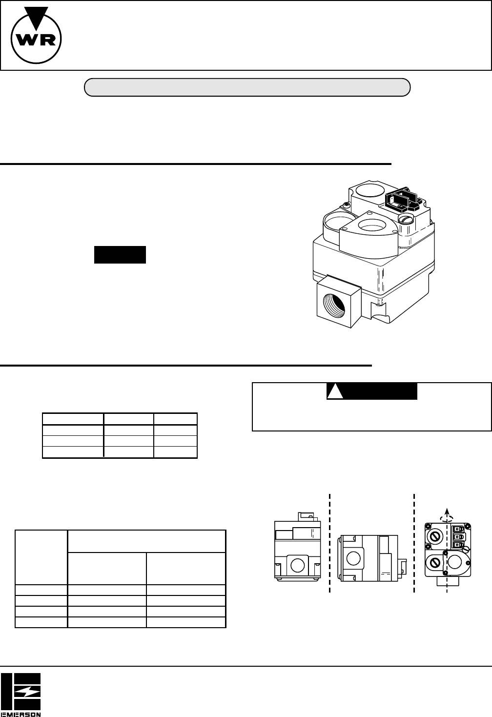
DESCRIPTION
NOTE
SPECIFICATIONS
Electrical Rating:
Main Valve
Maximum Pressure Rating:
14" W.C. (
1
⁄2 lb. per sq. in.)
Ambient Temperature: -40° to 175°F
Do not use this valve on indoor LP gas furnaces
except with 100% shut-off system.
Mounting: Any position except upside-down
CAUTION
!
PIPE SIZES/CAPACITIES
Pipe Size
(inches)
Capacity (BTU/hr) at
1” pressure drop across valve
1
⁄
2
” x
3
⁄
8
”
1
⁄
2
” x
1
⁄
2
”
1
⁄
2
” x
3
⁄
4
”
3
⁄
4
” x
3
⁄
4
”
100,000
230,000
230,000
280,000
162,000
372,600
372,600
453,600
Nat. Gas
(1000 BTU/cu. ft.,
64 Sp. Gr.)
LP Gas
(2500 BTU/cu. ft.,
1.53 Sp. Gr.)
MOUNTING POSITIONS:
Upright, 90° from upright or vertical
INLET BOSS
UP OR DOWN
UPRIGHT
LEFT OR RIGHT
360°


