


3
SYSTEM WIRING
To prevent electrical shock and/or equipment
damage, disconnect electrical power to system at
main fuse or circuit breaker box until installation
is complete.
All wiring should be installed in accordance with local
and national electrical codes and ordinances.
Always check that the electrical power supply used
agrees with the voltage and frequency shown on the
gas control.
These typical wiring diagrams (figs. 2 and 3) show only the
terminal identification and wiring hook up. Always refer to
wiring instructions provided by equipment manufacturer
for system hook-up and operation.
INSTALLATION
MAIN PIPING CONNECTIONS
Failure to turn off electric or main gas supply to
heating system could cause personal injury and/
or property damage by shock, gas suffocation,
fire, and/or explosion.
1. Turn off electrical power to the system at the fuse box
or circuit breaker. Also turn off the main gas supply.
2. If replacing an existing valve, disconnect all plumbing
and electrical connections from the old control.
3. The control may be installed in any orientation except
upside down. The arrow on the valve indicates the
direction of gas flow through the control.
4. You should use new pipe that is properly chamfered,
reamed, and free of burrs and chips. If you are using
old pipe, be sure it is clean and free of rust, scale,
burrs, chips, and old pipe joint compound.
5. Apply pipe joint compound (pipe dope) or teflon tape
that is approved for all gases, only to the male
threads of the pipe joints. DO NOT apply com-
pound or teflon tape to the first two threads (see fig. 1
for typical piping connections).
6. If you are using a vise or open-end wrench to hold the
valve while installing piping, do not tighten exces-
sively, as this may damage the valve.
7. See SYSTEM WIRING when making electrical con-
nections. After all gas and electrical connections are
completed, turn gas on and check for gas leaks with
leak detection solution or soap suds. Bubbles forming
indicate a leak. SHUT OFF GAS AND FIX ALL
LEAKS IMMEDIATELY.
All piping must comply with local codes, ordinances,
and/or national fuel gas codes.
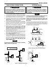
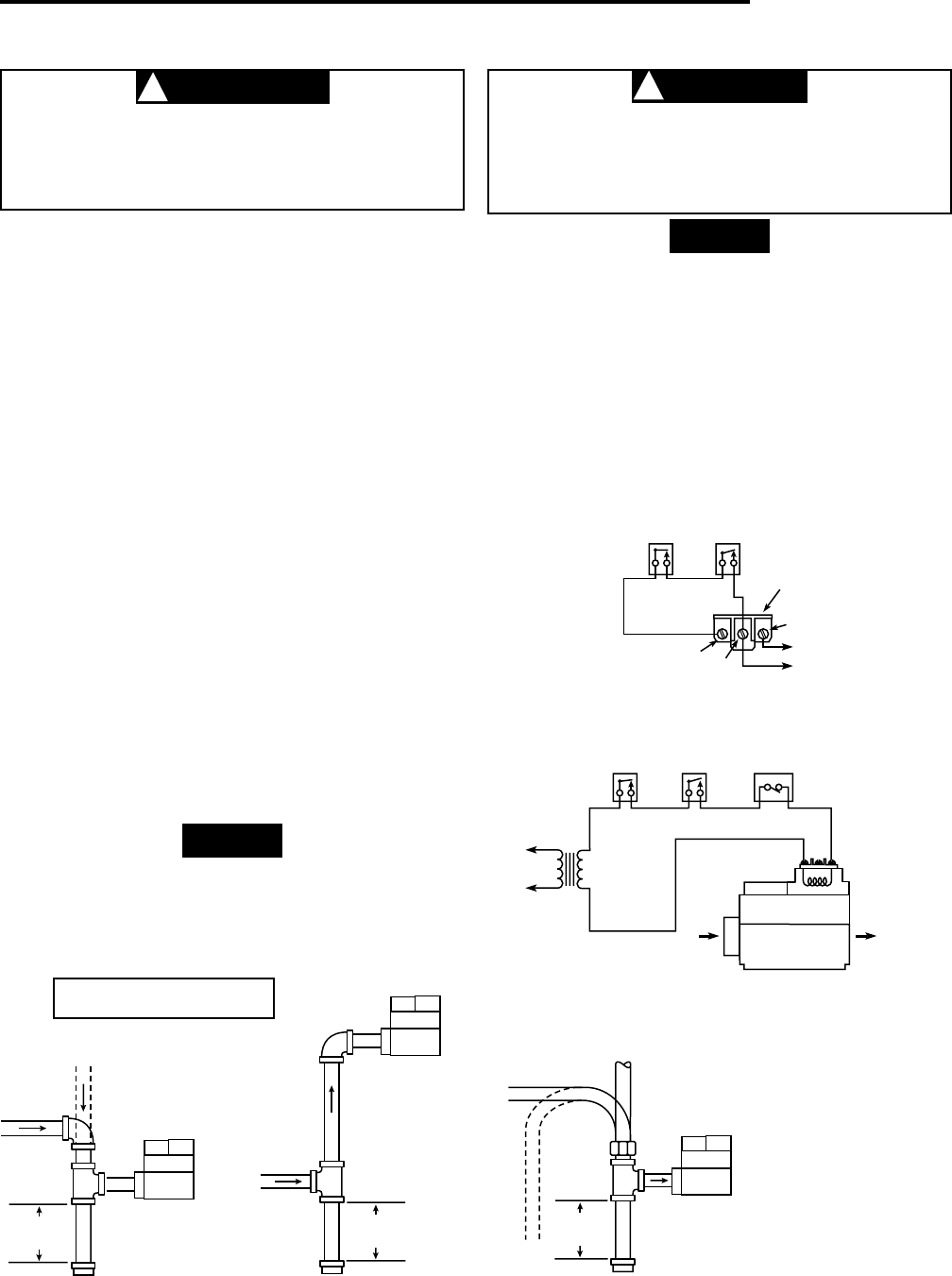
Thermostat
24 VAC
Gas
Valve
High
Limit
36C21
Valve
Automatic
Pilot
Figure 3. Wiring for 36C21 and 36C21A Models
NOTE
WARNING
!
CAUTION
!
NOTE
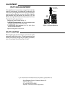
Piped Gas
Supply
Piped Gas
Supply
Tubing Gas
Supply
NOTE: ALWAYS INCLUDE A
DRIP LEG IN PIPING
Figure 1. Typical gas valve piping
Horizontal
Drop
Gas Valve
3 in.
minimum
Gas Valve
Riser
3 in.
minimum
Drop
Horizontal
Riser
Gas Valve
3 in.
minimum
High
Limit
To Pilot
Generator
TH
TH-TR
TR
Thermostat
Gas Valve
Terminal Panel
ALL WIRING
MUST BE
N.E.C. CLASS 1
Figure 2. Wiring for 36C21U