


2
1234
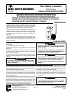
DIAPHRAGM
GAS VALVE
THERMOSTAT
TRANSFORMER
TO
LINE
AUTOMATIC
PILOT
IF AUTOMATIC PILOT IS NOT USED,
CONNECT A JUMPER BETWEEN
THE PILOT TERMINALS
LIMIT
CONTROL
THERM PILOT TRANS
Used as high limit
control with
diaphragm gas valve
If the boiler or burner manufacturer recommends a wiring
diagram, then follow such recommendations.
If none is offered, these diagrams show suggested circuits.
HOT
LINE
N
LOAD
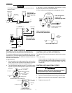
TYPE
230-19
TEMPERATURE
CONTROL
Used as operating control
for electrically heated tank
“B” Fixed
indicator
“A” Adjusting
slot
“E” Stop screw
“F” Stop tab
FIXED DIFFERENTIAL
“B” Fixed indicator
(cut-in point)
“C” Differential adjusting
screw
“D” Movable indicator
(cut-out point)
“A” Adjusting
slot
“E” Stop screw
“F” Stop tab
ADJUSTABLE DIFFERENTIAL
CONTROLS WITH ADJUSTABLE DIFFERENTIAL
The movable indicator points to the temperature at which the
contacts open. The fixed indicator points to the temperature at
which the contacts close. The difference between these two
indicators is the differential.
To set the control:
1. Use a screwdriver in the adjusting slot (A) on the front of the
control to turn the dial so that the fixed indicator (B) points
to the temperature at which the contacts will close.
2. Turn the differential adjusting screw (C) until the movable
indicator (D) points to the temperature at which the contacts
will open.
CONTROLS WITH A FIXED DIFFERENTIAL
The indicator (B) points to the temperature at which the contacts
open.
To set the control:
Use a screwdriver in the adjusting slot (A) on the front of the
control to rotate dial until the desired temperature at which
the contacts will open is positioned directly under the
indicator (B).
CONTROLS WITH ADJUSTABLE STOPS
Setting stop higher than control being replaced could
cause personal injury and/or property damage.
1. Loosen stop screw (E) with enclosed wrench.
2. Set dial to original equipment manufacturer's specification.
3. Without moving the dial, move stop tab (F) against indica-
tor.
4. Retighten stop screw (E).
CAUTION
SETTING THE CONTROL
NOTE
All wiring should be done according to local and national
electrical codes.
WIRING
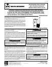
THERMOSTAT HIGH LIMIT
GAS VALVE
TERMINAL PANEL
TR
HOT
LINE
N
24VAC
TRANSFORMER
TH
TH-TR
Used as high
limit control with
36C03 Type Gas
Valve
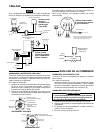
THERMOSTAT
TYPE 668
OIL BURNER CONTROL
IGNITION
TRANSF.
ORANGE
WHITE
LIMIT
CONTROL
BURNER
MOTOR
HOT
LINE
N
BLACK
Used as high
limit control with
oil burner control