


2
INSTALLATION CONT.
3. Insert sensing bulb into well, forming capillary so bulb
bottoms in well. Raise control onto well, slipping
flange on well between back of case and well clamp.
Be sure well fits snugly into hole in case. Then tighten
well clamp screws evenly and securely.
Do not dent or bend the bulb of the temperature
sensitive element as this will prevent it from fitting
properly into the well.
For best control performance it is recommended that
the existing well be replaced with a well shown on
page 3. However, by using the heat conductive grease
supplied in tube, these controls will give satisfactory
performance when used with larger-diameter existing
wells of many controls.
Use of adaptor requires that the existing immersion well
be equipped with a set screw. After removing old control,
install new one as follows:
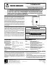
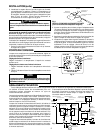
DIAL SETTING
When replacing an existing control, adjust settings to
correspond with those of the old control.
Setting the High Limit
Set pointer to temperature at which contacts are to open.
Setting the Low Limit-Circulator
1. Set brass pointer to lowest temperature of cycle.
2. Set aluminum pointer to highest temperature of cycle.
Always set the high limit 20° or more above the low
limit.
NOTE
Fig. 2
If boiler temperature exceeds the setting of the high limit,
the burner motor stops. If thermostat is calling for heat,
the circulator continues to run.
200 180
160
100 120 140
HIGH LIMIT LO LIMIT - CIR.
SET HIGH LIMIT 20° OR MORE
ABOVE LOW LIMIT
140160
180
240220200
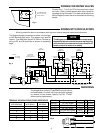
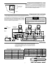
WIRING AND OPERATION
All wiring should be done in accordance with local and national electrical codes and ordinances.
The diagram below shows wiring connections for a typical
oil-fired installation. Operation is as follows:
When the room thermostat is not calling for heat, the low
limit-circulator control operates the burner motor as
necessary to maintain the domestic hot water supply at
the desired temperature (burner “on” when R-B contacts
are closed).
When the room thermostat closes its contacts, the relay
coil is energized and closes its two sets of relay contacts.
The burner starts as the No. 1 Relay Contacts close. If the
R-W contacts of the low limit-circulator control are closed,
the circulator motor also starts as the No. 2 Relay
Contacts close. If the R-W contacts open while the
thermostat is calling for heat, the circulator motor stops
but the burner stays on.
When the room thermostat is satisfied, the circulator
motor stops as the No. 2 Relay Contacts open. The
burner motor also stops as the No. 1 Relay Contacts
open, unless the R-B contacts of the low limit-circulator
are closed.
R
B
W
T2
S2
S1
1
ZC
ZC
2
C2
C1
B2
B1
Z
T1
Fig. 3
Line Voltage
Low Voltage
Line Voltage
Low Voltage
EXTERNAL WIRING
INTERNAL WIRING
TRANSFORMER
RELAY
COIL
TYPE 668 OIL
BURNER CONTROL
(LINE VOLTAGE)
IGNITION
TRANS.
BURNER
MOTOR
CIRCULATOR
MOTOR
#2 RELAY
CONTACT
LOW LIMIT-CIRC.
CONTROL
#1 RELAY
CONTACT
HIGH
LIMIT
HOT
LINE
N
LOW VOLTAGE
THERMOSTAT
ALUMINUM
POINTER
BRASS
POINTER
POINTER
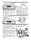
1.
Remove cover and loosen two screws holding well clamp.
2. Fit capillary into slot in adaptor and push adaptor
snugly into opening in back of case so adaptor flange
fits between well clamp and case. Then tighten well
clamp screws evenly and securely.
3. Apply heat conductive grease (supplied in tube) to fill
void between bulb and well.
4. Insert bulb into existing well, forming capillary so bulb
contacts bottom and side of well. Attach control to well by
tightening set screw securely. (Be sure set screw is not
directly above slot in well adaptor before tightening.)
CAUTION
ADAPTOR
FLANGE
WELL
CLAMP
CONTROL CASE
WELL ADAPTOR
(F71-0924)
CAPILLARY
BULB
Fig. 1
MOUNTING TO EXISTING WELL
(for types with well adaptor)