


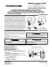
Operator: Save these instructions for future use!
FAILURE TO READ AND FOLLOW ALL INSTRUCTIONS CAREFULLY BEFORE IN-
STALLING OR OPERATING THIS CONTROL COULD CAUSE PERSONAL INJURY
AND/OR PROPERTY DAMAGE.
DESCRIPTION
SPECIFICATIONS
This compact zone valve is intended for use with a low voltage
system; do not use this zone valve with a millivolt or line voltage
system. If in doubt about whether your wiring is millivolt, line or
low voltage, have it inspected by a qualified heating contractor
or electrician.
Do not exceed the specification ratings.
All wiring must conform to local and national electrical codes and
ordinances.
To prevent electrical shock and/or equipment damage,
disconnect electric power to system at main fuse or
circuit breaker box, until installation is complete.
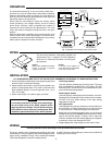
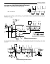
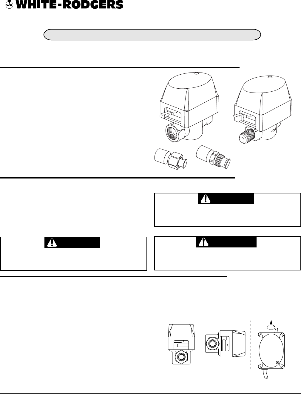
The compact zone valves are 2-way straight through, available
as a normally open or normally closed valve. The zone valves
come with or without a SPST normally open auxiliary switch and
feature a swing-type ball valve, which is designed to rotate which
causes the ball plug to seat on a different section of its surface
on each closing. They are available in several piping options,
sweat, NPT, inverted flare and flare fitting end connections for
standard copper tubing, for use with 2-wire thermostats. These
zone valves provide a low cost system of zoned temperature
control wherever hot water is the heating medium. In new
construction, the piping system can be laid out to produce any
number of independent temperature controlled zones by use of
these valves. In existing buildings, a variety of zone combina-
tions can be obtained, depending on the particular piping layout.
Each zone requires one zone valve and one thermostat, but only
one circulator is normally required for the entire system.
PRECAUTIONS
To prevent injuries from scalding always drain system
before installing or removing valve. To avoid gear damage
operate lever slowly.
Do not use on circuits exceeding specified voltages.
Higher voltages will damage control and could cause
shock or fire hazard.
All guarantees are void if these specifications are exceeded.
Maximum System Pressure: 142 PSI
Differential Across Valve: 20 PSI
Maximum Water Temperature: 230°F
Minimum Water Temperature: 41°F
Maximum Ambiant Temperature: 140°F
Approx. Time Cycle: 10 seconds from full close to full open;
4 seconds from full open to full close.
Electrical Rating:
Valve motor – 0.35A @ 25VAC, 50/60 Hz., 6 W nominal
Auxiliary switch: 3.0A Max. @ 25VAC
Thermostat: Use two-wire heating thermostat, .35A heat
anticipation is required.
Flow Coefficient - Cv Rating:
1/2" valves – 3.5 Cv (3.0 Kv)
3/4" valves – 3.5 Cv (3.0 Kv)
1" valves – 3.5 Cv (3.0 Kv)
INSTALLATION INSTRUCTIONS
COMPACT ZONE VALVES
2-WIRE, 2-WAY
For use on systems up to 142 PSI
CAUTION
CAUTION
WARNING
PART NO. 37-6334A
0142
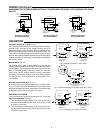
MAN
AUTO
UPRIGHT
LEFT OR RIGHT
INLET
UP OR DOWN
360°
Fig. 1 Zone valve mounting positions
MOUNTING POSITIONS:
Upright or 0° to 90° from upright
Flare Fittings
Available Separately
WHITE-RODGERS
EMERSON ELECTRIC CO.
9797 Reavis Road
St. Louis, MO 63123-5398
www.white-rodgers.com