


4
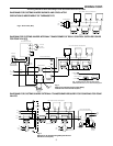
DIAGRAMS FOR SYSTEMS WHERE EXTERNAL TRANSFORMER REQUIRED FOR POWERING FOR ZONE
VALVES
WIRING (Continued)
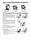
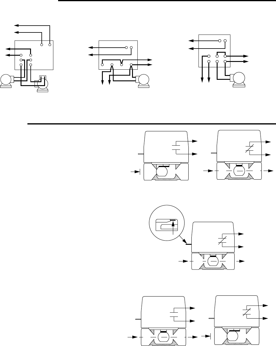
Automatic (AUTO) (N.C. valve) (Fig. 9)
On a call for by the thermostat, the valve opens and its auxiliary
contacts close, providing a low voltage auxiliary circuit for
starting the burner and/or circulator. After an elapsed time of
about 10 seconds, the valve reaches the full open position. The
valve motor now remains energized to keep the valve in the open
position. When the thermostat is satisfied, the valve closes by its
integral return spring. The auxiliary contacts open, de-energizing
the auxiliary circuit.
Manual (MAN)
(Fig. 10)
Use manual lever in case of power failure or for servicing the
system. If power fails while valve is open, valve will return to the
closed position. To manually open the valve, move the manual
lever to the "MAN" position and lock in place. The valve will
return to the "AUTO" position when the valve is electrically
energized. The auxiliary contacts close in the "MAN" position.
The manual lever is not operational on normally open (N.O.)
valve models.
Normally open models (N.O.) (Fig. 11)
A normally open valve operates opposite to a normally closed
valve. It is open in the de-energized position and closes when
the valve is energized. A reverse-acting (close-on-rise) thermostat
is required to control a normally open (N.O.)valve.
CHECKING THE SYSTEM
Turn on the electricity. If gas fired, be sure pilot is lit. Then check
each zone separately as follows:
1. Turn thermostat to highest setting. Zone valve for that zone
will open and furnace burner will come on as auxiliary circuit
is made on valve motor.
2. Turn thermostat to lowest setting. Zone valve for that zone
will close and furnace burner will shut off as auxiliary circuit
is broken on zone valve.
OPERATION
Fig. 10 Manual operation of normally close (N.C.) valve
VALVE CLOSED
POWER 'OFF'
VALVE OPEN
POWER 'ON'
Fig. 9 Normally close (N.C.) zone valve
VALVE OPEN
POWER 'OFF'
VALVE CLOSED
POWER 'ON'
Fig. 11 Normally open (N.O.) zone valve
VALVE OPEN, MANUAL POSITION
POWER 'OFF'
A B
AUXILIARY
SWITCH
N.O.
A
B
AUXILIARY
SWITCH
CLOSED
A B
AUTO MAN
AUXILIARY
SWITCH
CLOSED
A
B
AUXILIARY
SWITCH
N.O.
A B
AUXILIARY
SWITCH
CLOSED
THERM
1
6
3
4
5
2
T1T2
1
B2
C1 C2
2
B1
BLACK
BLACK
TO ZONE
VALVES
TYPE 8B42A OR 8B43A
N
LINE
HOT
CIRCULATOR
MOTOR
BURNER
MOTOR
IGN.
TRANS.
Alternate Connections
For Relay/Transformer
TYPE 829A RELAY
HOT
LINE
N
CIRCULATOR
MOTOR
TO GAS VALVE AND
TRANSFORMER OR
OIL BURNER
CONTROL
Alternate Connections
For Type 829A Relay
BLACK
BLACK
1 2 L L
TYPE 809A RELAY
HOT
LINE
N
CIRCULATOR
MOTOR
TO GAS VALVE
AND TRANSFORMER
OR OIL BURNER
CONTROL
Alternate Connections
For Type 809A Relay
BLACK
BLACK
RELAY/TRANSFORMER