


2
OPERATION
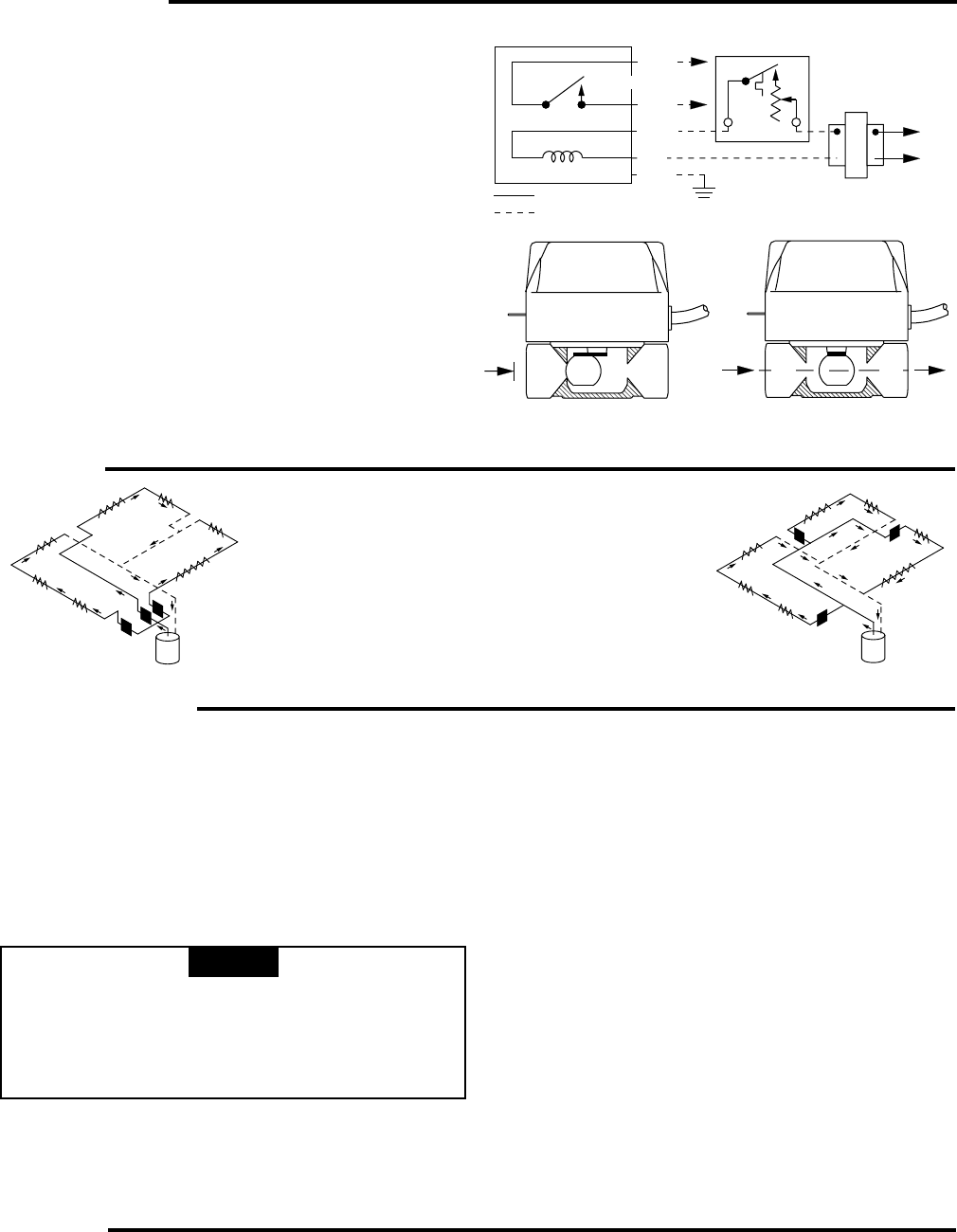
Fig. 4
PIPING
729
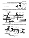
The two most commonly used piping systems are
shown below. Plan 1 is popular for new installations,
while plan 2 is frequently used when converting two-
pipe systems.
PLAN 1
Water valves installed at the boiler
header to provide a separate
supply to each zone.
PLAN 2
A common main supplies all
zones, with a water valve installed
on the riser to each zone.
Fig. 5
INSTALLATION
ALL GUARANTEES ARE VOID IF THE VALVE IS NOT ASSEMBLED ACCORDING TO THESE INSTRUCTIONS.
1. Disconnect electric power before connecting wiring to prevent
electrical shock or equipment damage.
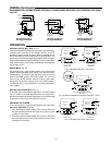
2. Select suitable valve location. Valve may be installed in any
position, except upside down. The arrow on the side of the
body indicates direction of flow throught the valve. (“A” is
inlet, “B” is outlet)
3. Mount valve directly in the tube or pipe, as follows:
For normally closed (N.C.) models, with sweat fittings,
set the manual lever to the "MAN" position before
applying heat to the fittings. This will protect the plug
ball inside the valve by removing it from the seat. After
installation, place manual lever in the "AUTO" position.
A B
A
B
VALVE CLOSED
VALVE OPEN
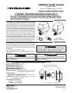
The schematic drawing Fig. 2 is for a normally closed valve.
As shown, the valve is closed and the thermostat is satisfied.
When the thermostat closes its contacts, the valve begins to
open as a circuit is made from the transformer to the motor and
thermostat, back to the transformer.
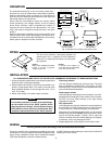
Shortly after the valve begins to open, the auxiliary switch
closes (providing a low voltage auxiliary circuit for starting
burner and/or circulator). After an elapsed time of about 10
seconds, the valve reaches the full open position. The valve
motor now remains energized to keep the valve in the open
position.
When the thermostat is satisfied, the circuit through the valve
motor is broken and a return spring begins to close the valve.
Just before the valve reaches the closed position, the auxiliary
switch opens to stop burner and/or circulator.
Fig. 3 Operation for normally close (N.C.) valve
NOTE
Flare fitting models
Use new, properly reamed pipe, free from chips. The valve
body is threaded for standard 5/8 in. OD copper, 45° SAE
flare-fitting nuts. These nuts are not furnished with the valve
and must be obtained separately.
Sweat copper models
Use new, properly reamed pipe, free from dents or corrosion.
Sweat the joints, keeping the outer surface free from solder.
DO NOT use silver solder because of the high melting
temperatures required.
NPT pipe models
Use new pipe that is properly chamfered, reamed and free of
burrs and chips. If using old pipe, be sure it is clean and free
of rust, scale, burrs, chips and old pipe joint compound.
Apply pipe joint compound or teflon tape, only to the male
threads of the pipe joint. DO NOT apply compound or teflon
tape to the first two threads. If using a vise or open-end
wrench to hold the valve while installing piping, do not tighten
excessively, as this may damage the valve.
4. Support piping with a pipe hanger on each side of valve.
WIRING
All wiring should be done according to local and national electrical codes
Follow any specific wiring instructions provided by the boiler
manufacturer. If none are supplied, the following diagrams offer
typical wiring installations using 2-wire heating thermostats
(.35A Heat-Anticipation) and other related controls.
A 40VA Transformer will handle up to 4 zone valves. A 20VA will
handle up to 2 zone valves.
TYPE 'Z' ZONE VALVE
AUX. SWITCH
MOTOR
INTERNAL WIRING
EXTERNAL WIRING
N.O. CONTACT
2-WIRE HEATING
THERMOSTAT
HOT
N
LINE
TRANSFORMER
Fig. 2
BLUE
BROWN
GREEN
BLACK
BLACK