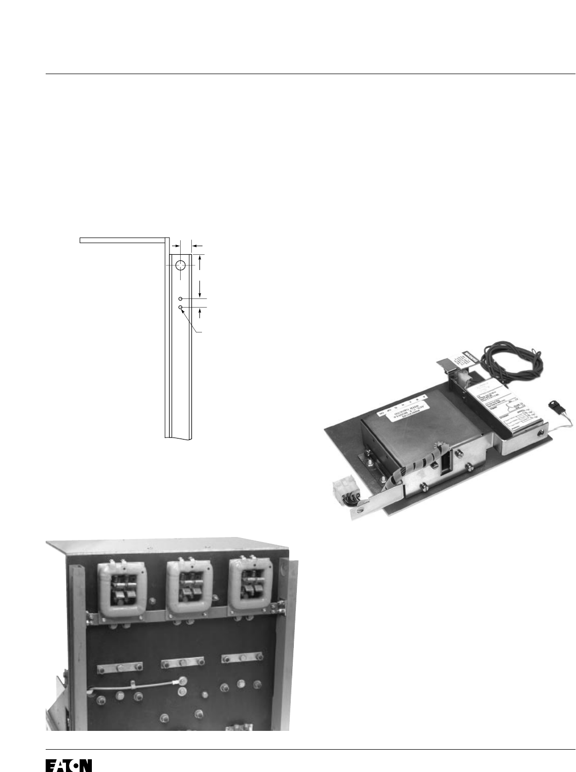
Step 4: Mounting the Sensor Assembly to the
Breaker
A. Using Drilling Plan “A”, drill two (2) .312" holes
in each of the Breaker Rear Channels.
B. Using the .250-20 × .750" bolts, flat washers,
lock washers, and hex nuts provided and the
holes just drilled, mount the Sensor Assembly
to the Breaker Rear Channels as shown.
Step 5: Assembling the Aux. CT Module
Platform
A. Remove two screws from each side of the
Auxiliary Current Transformer (Aux. CT)
Module. Using the original screws, attach the
Side Mounting Clips to the Aux. CT Module
as shown.
B. Using the .190-32 × .625" nylon screws, flat
washers, lock washers, and hex nuts provided,
mount the Aux. CT Module to the Glass Poly
Barrier so the Aux. CT Harness is near the
back of the Barrier as shown. Note that the
nylon screws must be inserted through the
Barrier first. Snug the nuts, being careful not to
strip the nylon screws.
C. Remove the two (2) self tapping screws
from the back of the Aux. CT Module. Using
the screws just removed and the two (2)
.190-16 × .500" thread cutting screws provided,
mount the Aux. CT Module Mounting Bracket
as shown. Note that the “U” shaped notch must
face upward so that the Aux. CT Harness is
unobstructed.
D.
For Kits Supplied with a PT Module Only
.
Using the .138-32 × .375" screws, flat washers,
lock washers, and hex nuts provided, mount
the Potential Transformer (PT) Module to the
Glass Poly Barrier as shown.
Effective December, 1998
IL 33-FC6-1
Page 4