MA250-EU-EN-V3.2-6/11
6
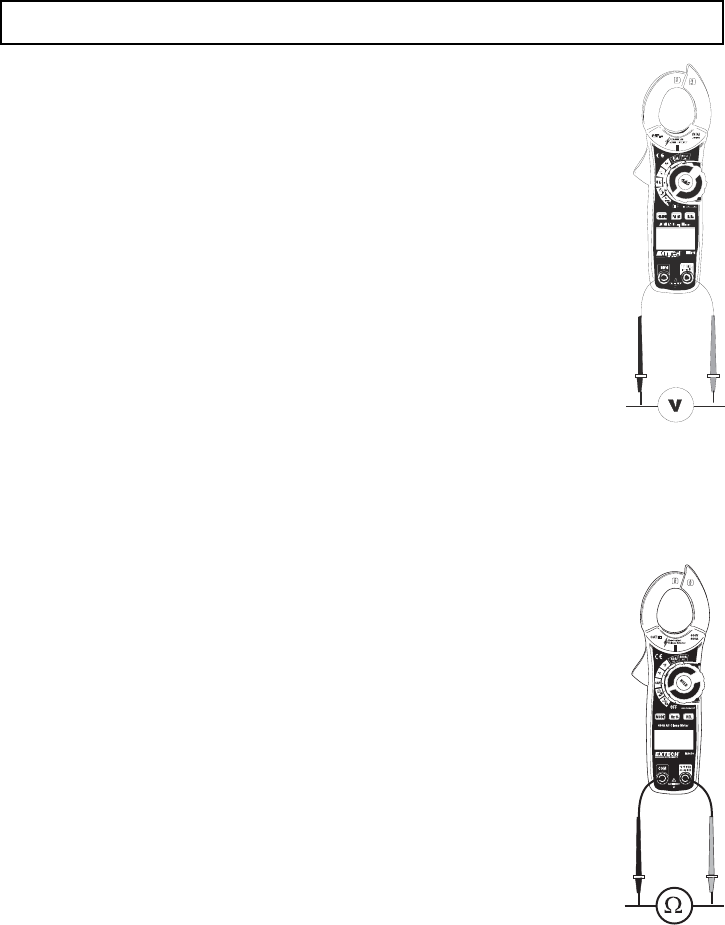
AC/DC Voltage, Frequency, Duty Cycle Measurements
CAUTION: Do not measure voltages if a motor on the circuit is being switched ON or OFF. Large
voltage surges may occur that can damage the meter.
1. Rotate the function switch to the V position.
2. Press the MODE button to select AC or DC Voltage.
3. Insert the black test lead banana plug into the negative COM jack.
Insert the red test lead banana plug into the positive V jack.
4. Touch the black test probe tip to the negative side of the circuit.
Touch the red test probe tip to the positive side of the circuit.
5. Read the voltage value in the display.
6. Press the Hz % button to display Frequency
7. Press the Hz % button to display Duty Cycle
Resistance, Diode, Continuity Measurements
Note: Remove power from the device under test before making resistance measurements
1. Set the function switch to the Ω position.
2. Insert the black test lead banana plug into the negative COM jack.
Insert the red test lead banana plug into the positive V jack.
3. Touch the black test probe tip to one side of the device.
Touch the red test probe tip to the other side of the device.
4. Read the resistance value in the display.
5. Press the MODE button to select the DIODE mode. The Diode symbol will
appear in the display.
6. Press the MODE button to select the Continuity mode. The continuity symbol
will appear in the display. If the resistance is <150 ohms the tone will sound.


