382068-EU-EN-V4.0 12/11
15
1
φ
3W power measurements are similar to 3
φ
3W
unbalanced power measurement except for the
nomenclature. Two measurements are required: W
RS
(L1G)
and W
TS (L2G)
.
A. Measure W
RS (L1G)
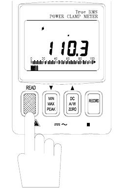
(refer to figure 11).
1. With the Clamp jaws empty, turn the meter on by
setting the rotary switch to the 3
φ
3W position.
2. Insert the test leads into the input terminals.
3. Connect the probe end of the black lead to
ground.
4. Connect the probe end of the red lead to the
second phase (eg. L1).
5. Clamp onto the second phase (eg. L1).
6. The meter will automatically select the proper
range.
7. Wait until the reading is stable (about 6 seconds)
and then press the READ button.
8.
WL23 will appear prompting the user to take the
W
TS (L2G)
measurement.
Figure 13
B. Measure W
TS
or W
L2G
(refer to figure 12).
1. Disconnect the red test lead from the phase where the jaws are clamped.
2. Connect the red test lead to the L2 line.
3. Clamp onto the L2 line (where the red test lead is connected).
4. The meter will automatically select the proper range.
5. Wait until the reading is stable (about 6 seconds) and then press the READ button.
C. The power clamp sums the
two values
, displays the result, and stores the 1
φ
3W power
measurement in memory. Note the following equation:
W
1φ3W
= W
RST
= W
RS(L1G)
+
W
TS(L2G)
600V
PF lag
3 3W
WL1 23
KW
MAX CAT
HOLD


