Your test jumpers must be cleaned and inspected prior to using them for fiber link testing. You should have
one jumper for the power meter side of the test, and one jumper for each of the connector ports on your light
source. Make sure that these patch cords match the fiber under test (i.e. same fiber type, same core/cladding
size, same connector type).
Use the following steps to set up your reference jumpers for link testing:
1 - Connect the first jumper to the power meter and light source. Verify that it is working properly and not
introducing significant loss to the test. Disconnect this patch cord from the light source and meter and set it
aside.
2 - Connect the other patch cord(s) to the light source. If you have a dual wavelength light source with two
connector ports, then it is recommended to connect one jumper to each port.
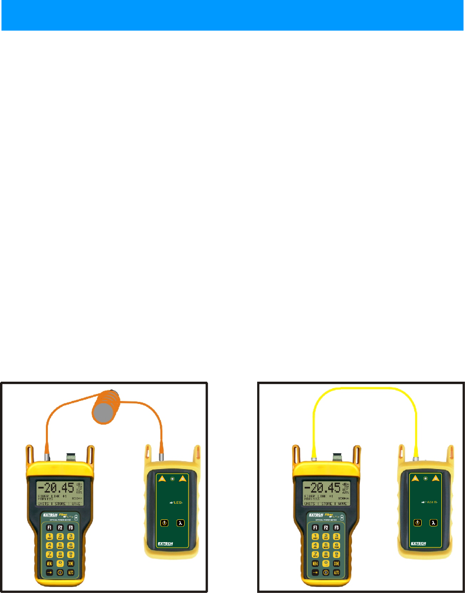
3 - MULTIMODE ONLY. If you are testing multimode fibers, you will need to wrap each of the jumpers
connected to the light source around a mandrel seven times. This is done to achieve Equilibrium Mode
Distribution (EMD), which eliminates unwanted optical energy that can cause inaccurate test results.
4 - Set the optical reference. See the appropriate unit for detailed instructions on setting each optical
reference method.
NOTE: Do NOT remove the patch cords from the light source until you have completed testing all of the fibers
in the link. Disconnecting the test jumper from the light source and re-connecting it will cause the optical
reference to be incorrect, thereby producing incorrect readings, and may cause a link to fail.
Singlemode
Reference
Multimode
Reference
Reference Cable Setup
5-8
Appendices
UNIT 5
Fiber Type) Mandrel Size
(3mm jacket)
62.5/125 0.7 inches
50/125 0.9 inches
CHARGER
850nm 1300nm
MULTI MODE
LIGHT SOURCE
DualDual
CHARGER
1310nm 1550nm
SINGLE MODE
LIGHT SOURCE
DualDual


