89
Chapter 7 Replacing Parts
3. Slide the HDD into the drive cage opening.
4. Connect the power and data cables to the disk drive.
For the IDE model, use the two connectors on the primary cable (IDE-1) to connect the IDE drives. The
secondary cable (IDE-2) is intended for the IDE CD-ROM and an optional IDE device (shelf 3) or third
drive (shelf 4).
For the SCSI model, use the SCSI cable, which has 5 connectors and a termination on the end of the cable.
Typically, the SCSI cable is already folded, allowing you to use the available connectors on the SCSI cable
nearest the drive cage.
5. Replace the left side cover.
6. Replace the external cables and power cord.
7. Power on the server as described in Chapter 1‚ Controls and Indicators.
8. Verify the new configuration by checking the HP Summary screen. To access the HP Summary Screen,
press F10 when the HP logo appears during startup.
DIMMs
Removing DIMMs
Use this procedure to upgrade DIMMs or replace a defective DIMM.
1. If the server is operating, power down the server.
Refer to Chapter 1‚ Controls and Indicators for instructions.
2. Disconnect the power cord and any external cables connected to the server.
If necessary, label each one to expedite re-assembly.
3. Remove the left side cover.
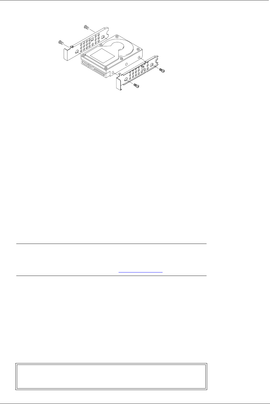
Figure 7-7. Attaching the Rails
NOTE Use only memory modules provided for your hp server model.
Install only 128 MB, 256 MB, 512 MB, or 1 GB buffered
ECC DDR DIMM modules. To ensure that you have the
correct DIMMS, refer to http://www.hp.com
.
WARNING The power supply will continue to provide standby current to
the hp server until the power cord is disconnected from the
AC power source.


