


Rev. 03/04
Rev. 03/04
Product
Specications
Operating
Information &
Display Symbols
Charts &
Accessories
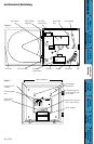
Instrument
Anatomy
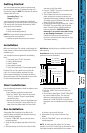
Getting
Started/
Installation
Keypad
Operation
Dip Switch
Setup &
Calibration
Troubleshooting
Warranty &
Returns
DICKSON
Power Supply:
We recommend using AC Power with one 9V battery
installed as a back-up power source. This ensures
that your recording will not be interrupted when
there is a power failure. The AC Adapter is built into
the back of the recorder. NOTE: When the unit is
in battery back-up mode, the recorder will update
temperature readings at a much slower rate. The
battery should be replaced once a year and after
power failures of more than a few hours.
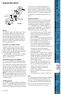
To Replace Battery:
1. Open the door of the recorder by depressing the
door latch.
2. Press the “HOME” key
3. Lift the chart, if there is one present, to fully
expose the battery compartment and press down
on the tab to release battery compartment door.
4. Replace 9V battery
Pen:
Hysteresis ( a property that occurs when tension is
applied to an object) causes the pens to move in
increments across the chart as the sensor readings
change. However, the display readings are not
affected by the property of hysteresis. For this
reason the display provides smoother and faster
readings than the pen. At any given time there may
be a slight discrepancy in the positions of the pens
and the readings on the display.
For visual spot checks the display is the
most accurate but both are within the stated
specications of the unit (see “Specications”).
Pens (2 pen KT6):
The blue pen has a longer pen arm than the red
pen. The pens are offset to allow the red pen to
glide under the blue pen. The blue pen indicates the
correct time and the red pen precedes it by 3/16 of
an inch.
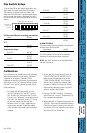
The SPST 24V 500mA relay contacts are normally open and will close on alarm conditions when the alarms
are enabled. Relay contacts are always functional when the alarm is enabled. Dip Switch #8 has no effect
on the relay. The relay will close only during minimum and maximum alarm conditions. 2 pen units have two
sets of relay contacts which operate independently.
NOTE: For compliance to CE directives, do not remove the rubber cover from the alarm relay terminals when
the terminals are not used.
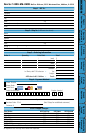
Figure 4
Operating Information
Alarm Relays
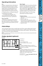
Display Symbols (optional)
C: Indicates ˚C
F: Indicates ˚F
0: Zero calibration mode
A: Alarms enabled or alarm set mode
MIN:
This symbol is displayed when you are setting a
minimum alarm or during a minimum alarm condition
(when alarms are enabled)
MAX:
This symbol is displayed when you are setting a
maximum alarm or during a maximum alarm
condition (MIN and MAX ash when the alarms are
enabled and no alarm condition exists)
1: Channel One
2: Channel Two
Two channel units only