


Rev. 03/04
Rev. 03/04
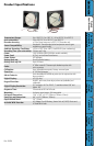
Product
Specications
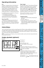
Operating
Information &
Display Symbols
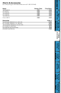
Charts &
Accessories
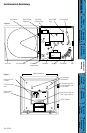
Instrument
Anatomy
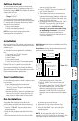
Getting
Started/
Installation
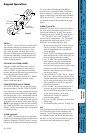
Keypad
Operation
Dip Switch
Setup &
Calibration
Troubleshooting
Warranty &
Returns
DICKSON
Dip Switch Setup
Calibration
Your instrument was carefully tested and calibrated
before being shipped from the factory. Additional
calibration is not required. However, should
calibration be desired in the future, we recommend
that it be at our lab. Call Customer Service at (630)
543-3747. If you wish to calibrate yourself, follow
these procedures:
1. To activate the calibration mode, turn the
unit OFF. Now press the “ON/OFF” key and
the “ALARM” key at the same time. The unit
is in the “User Calibration” mode when the red
LED is ON. The display will show a “C” during
the warm up period and then will ash
between 0 and F or 0 and C (depending on
measurement selected). Match the reading
of the recorder to the reading of the reference
standard.
2. To raise the unit of measurement, press the
“CHART ROTATION (UP ARROW)” key. To
lower the unit of measurement, press the
“HOME (DOWN ARROW)” key. To ensure
that you have matched the standard, allow
the pens to stabilize for at least 30 seconds
before exiting calibration mode. If your KT6
only has one pen, skip to Step 4.
3. Press the “ALARM” button for 2 seconds to
switch from Pen 1 to Pen 2. Repeat step 2 for
Pen 2 temperature calibration.
4. When calibration is complete, simply press the
“ON/OFF” key to save the calibration settings.
Calibration is stored in memory even after you
turn the unit OFF. User Calibration information
will not be lost if AC Power fails.
#7 OFF
0 to 250˚ #5 ON
#6 ON
#7 OFF
0 to 500˚F (only ˚F) #5 OFF
#6 OFF
#7 ON
-50 to 50 #5 ON
#6 OFF
#7 ON
0 to -50 #5 OFF
#6 ON
#7 ON
0 to -100 #5 ON
#6 ON
#7 ON
ALARM SPEAKER:
The alarm speaker may be activated or deactivated
with the use of Dip Switch #8
Deactivated #8 ON
Activated #8 OFF
The Alarm Speaker will sound during minimum,
maximum or probe missing alarm conditions.
NOTE: dip switch settings are only updated when
the unit is turned on.
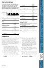
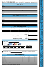
To set up the KT6 for your specic application, you
might need to change some of the Dip Switches.
The switches are located under the chart in the
lower half of the dial plate. A pointed object can be
used to change the settings. Remember to install
the correct chart to match corresponding dip switch
setting.
KT6 has two different recording time options
1 day #3 ON
7 day #3 OFF
˚F/˚C
˚C #4 ON
˚F #4 OFF
Temperature Range
0 to 100˚ #5 OFF
#6 OFF
#7 OFF
0 to 50˚ #5 ON
#6 OFF
#7 OFF
50 to 100˚ #5 OFF
#6 ON
Slide toggle to this side for ON
Slide toggle to this side for OFF
1
2
3
4
5
6
7
8
All switches are
shown in OFF
position.