


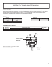
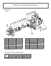
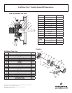
IntelliGear Plus™ Variable Speed MD Gearmotors
11
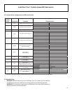
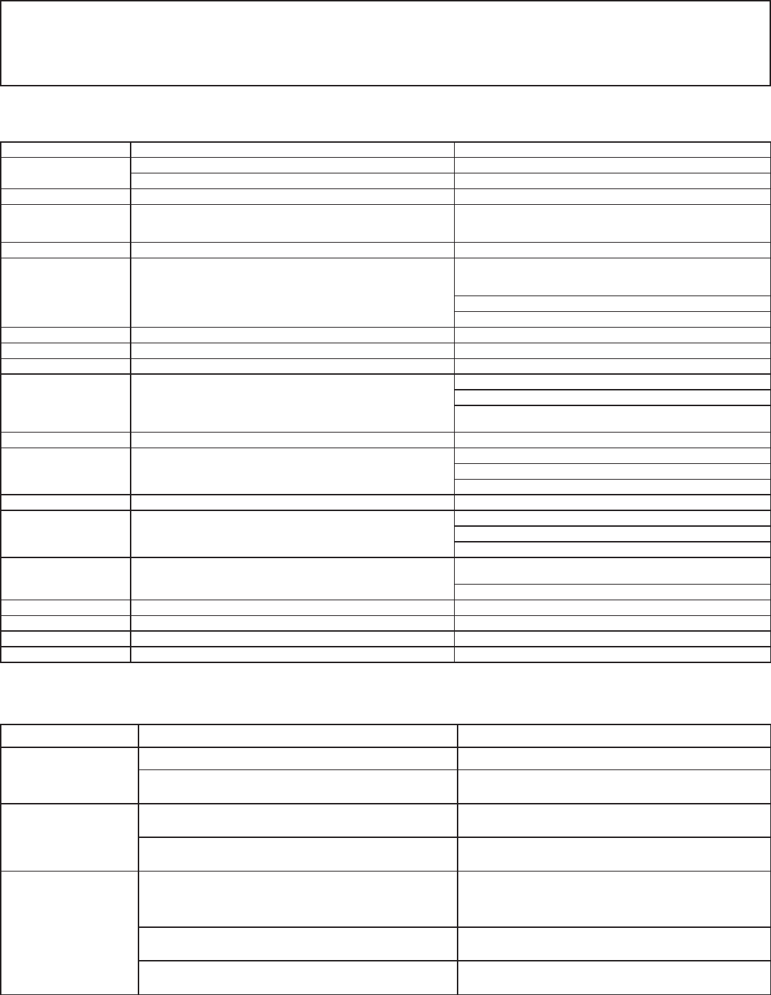
5. 1 Fault Mode Troubleshooting Guide
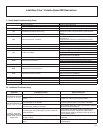
5.2 Additional Troubleshooting
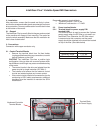
LED Pad Display Drive Status/Fault Indication Actions Required
Blank Display
Drive not powered Check for drive input power
Display unplugged or failed Check display plug connection
0019 - 0600 Numeric display shows Pump RPM, indicates motor running
rdY Drive Ready (Enabled & Not Running)
In AUTO mode, make sure AUTO-RUN contact is closed
between pins 5 & 6 of 6-pin connector if pump should be
running
inh Drive Inhibited (Not Enabled) Install jumper between IntelliGear terminals 11-12
tr01 Motor thermostat trip - Overtemp
Check motor thermostat connections between IntelliGear
terminals 5 & 9
(Install jumper if motor has no thermostat wires -P1/P2)
Check motor fan & clean debris or obstruction to air ow
Check for motor overload
tr02 Internal brake resistor trip - Overtemp Contact factory
tr03 Pump RUN DRY or HIGH PRESSURE fault trip Check for proper ow and pressure in pump
UU DC Bus Undervoltage Check incoming power for voltage level too low
OU DC Bus Overvoltage
Check incoming power for voltage level too high
Check for over-running load (pressure over-driving pump)
Adjust drive parameter 04 (deceleration time) to a higher
setting using drive keypad/display
ph.AC Loss of a motor phase Check motor connections at IntelliGear grey terminal strip
OI.AC Overcurrent at Drive Output
Check motor connections at IntelliGear grey terminal strip
Check for ground fault or line-line fault in motor wiring
Check for moisture or insulation damage in motor windings
It.AC Motor Overload (I X t) Check for excessive torque load at pump
Oht1 Overheating in Output Transistors
Check heatsink ns for debris or obstruction to air ow
Provide supply of cool air if ambient exceeds 40°C
Reduce torque load from pump
Oht2 Overheating in Brake Transistor
Adjust drive parameter 04 (deceleration time) to a higher
setting using drive keypad/display
Reduce start/stop frequency
rS Stator Resistance Measurement Fault Check motor connections at IntelliGear grey terminal strip
SCL Serial connection between keypad and drive broken Check display plug connection
EEF EEPROM fault in drive Contact factory
OI.br Overcurrent at Brake Transistor Contact factory
Symptom Probable Cause(s) Actions Required
Not Running, No Fault
Indication on Display
Drive not in HAND or AUTO mode Press HAND or AUTO button on Keypad
Drive in AUTO mode, but AUTO-RUN contact not
closed
Close AUTO-RUN contact or
Jumper pins 5-6 on 6-pin connector cable
Unit Runs Only at Low
Speed in AUTO mode
4-20 mA signal is not present
Connect 4-20 mA signal and Verify that the signal
current is present (pins 1 & 2 of 6-pin connector)
4-20 mA signal polarity is reversed
Verify current enters pin 1 of 6-pin connector Reverse
the connections if necessary
In AUTO, Unit Does
Not Achieve Maximum
Output RPM at 20 mA
Signal Input
4-20 mA signal not achieving full 20 mA at maximum
speed reference
Signal source may not be capable of producing 20
mA with the drive input impedence of 500 ohms -
must be able to produce at least 10 VDC at pin #1 of
6-pin connector cable
Maximum speed setting of operator keypad setting is
not set to 100%
Press UP ARROW on keypad until maximum speed
is attained
IntelliGear MAXIMUM SPEED setting has been turned
down
Adjust drive parameter 02 to 2700 RPM using drive
keypad/display