


IntelliGear Plus™ Variable Speed MD Gearmotors
7
2 - Installation
After connection, ensure that the seals are firmly in place,
and that the screws and cable glands are watertight to ensure
drive protection. Clear any condensation from the drain holes
at the bottom of the motor.
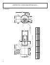
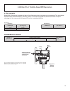
2.1 - General
The IntelliGear Plus is usually fitted to the gear and mounted
to the machine with flange or foot mounting. The motor fan
cools the whole assembly. Make sure that the ventilation air
inlet is free of obstruction.
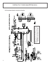
3 - Connections
Connection with copper conductor only.
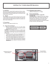
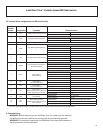
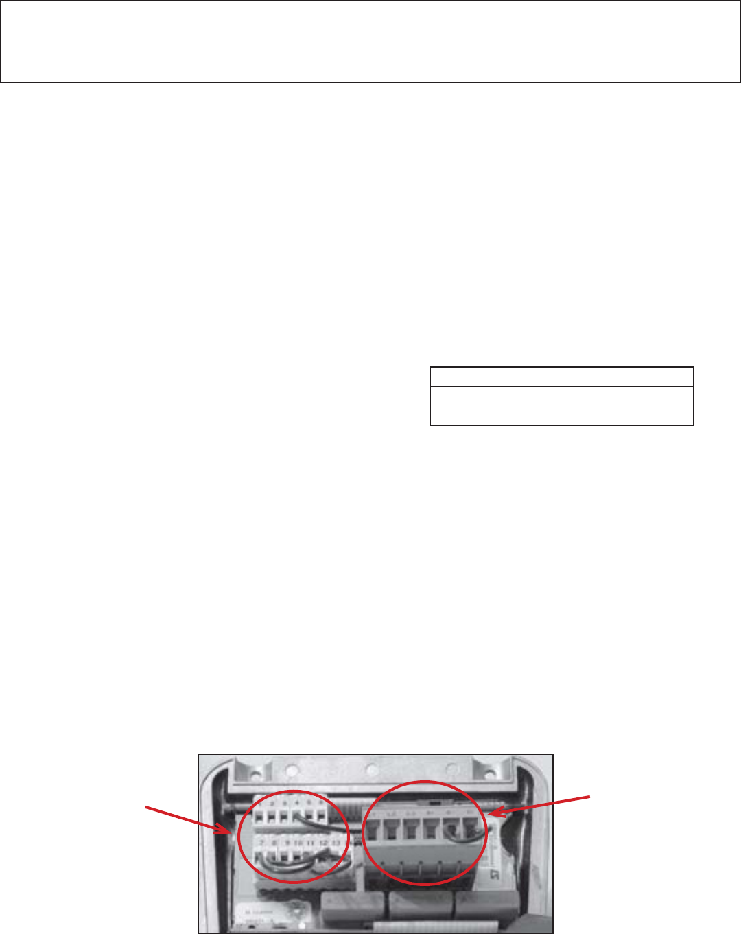
3.1 - Control Terminal Blocks
• Remove the terminal block from it’s fixed holder
(unplugged) before making any connections, to avoid
putting pressure on the card.
CAUTION: The IntelliGear Plus has a positive logic
configuration. Using a drive with a control system which
has a different control logic may cause unwanted starting
of the motor.
• The control circuits in the drive are isolated from the
power circuits by single insulation (IEC 664-1).
• The installer must ensure that the external control
circuits are isolated against any human contact.
• If the control circuits need to be connected to circuits
conforming to SELV safety requirements, additional
insulation must be inserted to maintain the SELV
classification.
Removable screws in terminal block:
• Tightening torque = 2.62 in. lbs.
• Maximum cross section = 17 AWG
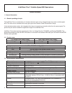
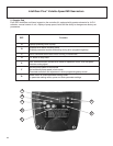
3.2 Power terminal blocks
3.2.1 Terminal block for power supply PB1
(marked L&N)
This terminal block is used to connect the 3 phase
power supply when the RFI filter is not used in an
IntelliGear Plus. Otherwise, the RFI filter output
is screwed onto this connector and the power
supply should be attached to the terminals located
on top of the filter. (See table below)
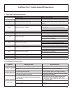
Screw terminal blocks 310M & 31M
Tightening Torque 7.1 in. lbs.
Max. cross-section AWG 14
Numbered Controller
Terminal Blocks
Terminal Block
for Power Supply