


PO. Box 726 n TULSA, OK 74101 n TEL 918-627-5530 n FAX 918-641-7336 n www.nelsonheaters.com
GA-2318, R1
Sheet 4 of 15
May 2008
Installation & Operating Instructions
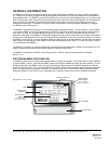
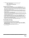
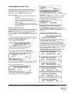
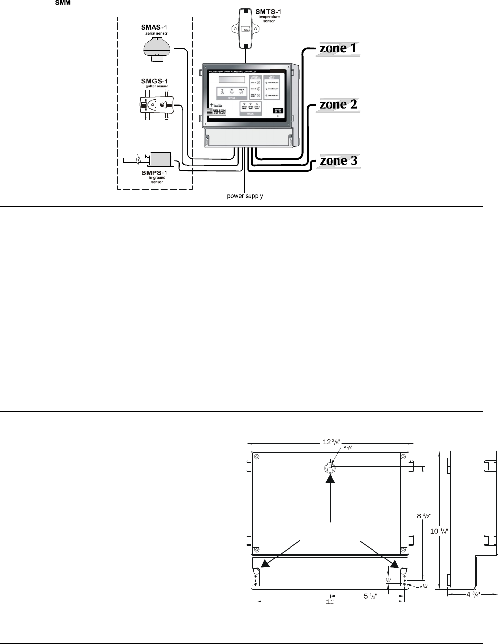
120 VAC, to contactor coils
snow/ice
sensor
options
maximum 2 sensors
per zone
*
*maximum 1 SMPS-1 sensor per zone
120 VAC, 450 VA
power contactors(s)
power contactors(s)
power contactors(s)
Fig.2
Sample Application Illustration
C
-3
SMMC-3
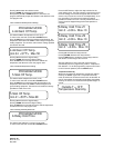
WARNINGS
1. A qualified electrician must install the SMMC-3.
2. If after carefully reading these instructions you still
have questions regarding installation operation or
maintenance of this product, call the numbers listed
for assistance.
3. Prior to installation, check the SMMC-3 Control
Panel for possible shipping damage. Do not install a
damaged SMMC-3 Control Panel.
4. All heating equipment, controls & associated
systems must be installed in compliance with the
latest editions of all applicable electrical codes and
ordinances.
5. The SMMC-3 has been designed to accept only
Nelson moisture and temperature sensor inputs.
The risk of fire or electric shock exists if the SMMC-
3 is connected to any device other than a Nelson
sensor.
6. Do not connect heating equipment directly to the
SMMC-3 Control Panel. The SMMC-3 control relays
provide an output to operate external contactors. Each
output provides a maximum current output of 1.25A.
The risk of fire or electric shock exists if the heating
equipment is directly connected to the SMMC-3 Control
Panel.
7. These instructions must be saved and made available
to owners or users of this product and/or transferred to
future owners.
8. Secure the SMMC-3 in an accessible location. The
SMMC-3 Control Panel is not suitable for installation
environments subject to condensing moisture or those
exposed to temperature extremes.
9. Avoid shock or vibration.
INSTALLATION
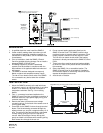
1. Mount the SMMC-3 securely to the wall with three
#10 screws, mount in an upright position in an indoor
location, in an area that is dry and not subject to
temperature extremes. See Fig. 3 for mounting
details.
2. Four ½” connectors have been installed on the
SMMC-3 Control Panel box to facilitate connection of
electrical conduit for input power supply wiring, and
contactor output wiring.
3. Remove the lower front access cover to begin
connecting wiring. On the back of the access cover is
a wiring guide label.
4. Connection to the SMMC-3 is done through terminal
blocks. Fish the wire being connected through the
adjacent knock-out, and pull out approximately 12” of
wire. The top half of the terminal block is removable
for easy wiring; gently pull up on the top half to
remove. After connecting the wire to the top half
gently set it back into the base while carefully pulling
back excess wire through the knock-out.
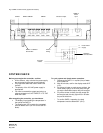
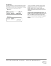
Fig.3
Mounting: mounts to wall via three #10 screws
mounting screw
locations