


PO. Box 726 n TULSA, OK 74101 n TEL 918-627-5530 n FAX 918-641-7336 n www.nelsonheaters.com
GA-2318, R1
Sheet 6 of 15
May 2008
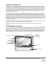
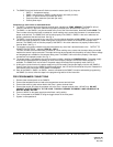
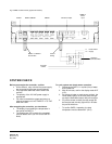
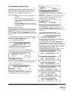
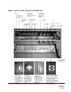
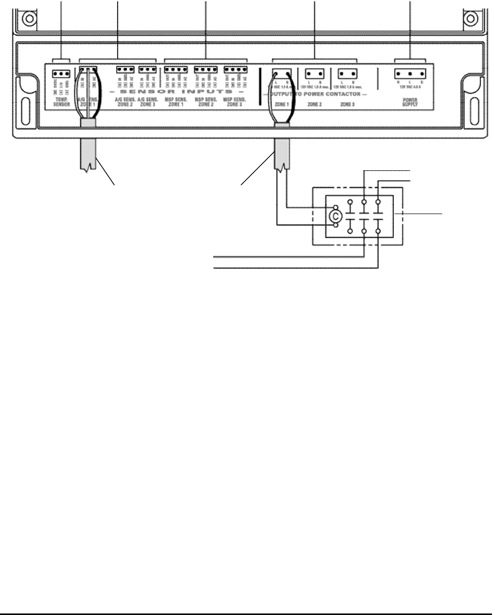
Fig. 4 SMMC-3 Control Panel (Typical Connections)
SYSTEM CHECK
Before you energize the controller, confirm:
· All the sensors, relay coils and the power supply
are connected to the proper terminal blocks.
· Only approved cable was used to extend the
sensors.
· The polarity of the 120 VAC power supply is
appropriate.
· You have connected the output terminals to a
relay or contactor coil, NOT DIRECTLY TO THE
HEATER LOAD.
After energizing the controller, you should see:
· The display lit and reading the temperature in
the area of the SMTS-1.
· The Small green LED’s next to the connected
terminal blocks are lit (no LED for the SMTS-1
block).
To cycle system and check sensor operation:
1. Submerge the SMTS-1 in a quart (litre) of water
and crushed ice.
2. After 20 minutes, confirm the display reads 32°F
(0°C).
3. Put a drop of water on each sensor surface*, the
Power Relay light(s) on the front panel will light
up and the associated output relay will energize.
4. Dry off the sensor surface; the relay output will
de-energize and the relay light will turn off after
the pre-set hold time.
* To confirm SMPS-1 operation, the slab
temperature must be below 59°F (15°C).
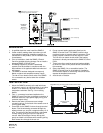
SMTS-1 SMAS-1/SMGS-1 SMPS-1 Contactor Output
SMMC-3
Power
Input
L1
L2
Heater Power
Sup
ply
Contactor/
Connection Box
SMAS-1 or SMGS-1
Sensor Wire
Control
Wiring
To Heater
Cables