


9
External buzzer (option)
The optional external buzzer provides a louder
alert when the guard alarm is violated.
External buzzer
Type: OP03-168
Code No.: 008-462-790
Name Type Code no. Qty
MJ-XH
connector
03-2022 (2-3P) 008-463-540 1
Buzzer
assy.
80-0641 008-462-800 1
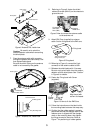
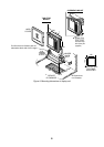
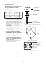
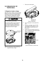
1. Unfasten screws and connector nuts to
remove the rear cover from the display unit.
2. Place the rear cover on a workbench, out
side up. Remove the plastic hole cover from
the location shown in Figure 19 with a
Phillips screwdriver and a hammer.
Remove burrs from the hole with a fine file
or sandpaper.
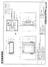
3. Insert the MJ connector (supplied as
option) in the hole made at step 2 as shown
in Figure 17. And then fasten the connector
nut with 0.76-0.78 N
•
m torque.
4. Plug in the XH connector at the end of
above connector into J6 on the DU Board.
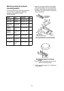
5. Fasten screws and connector nuts to
reassemble the display unit. Torque should
be between 0.76-0.78 N
•
m.
6. Fasten the buzzer near the display unit
(within 1 m) with two tapping screws (3X15
or 3X20; local supply).
7. Attach the connector from the external
buzzer to the MJ connector.
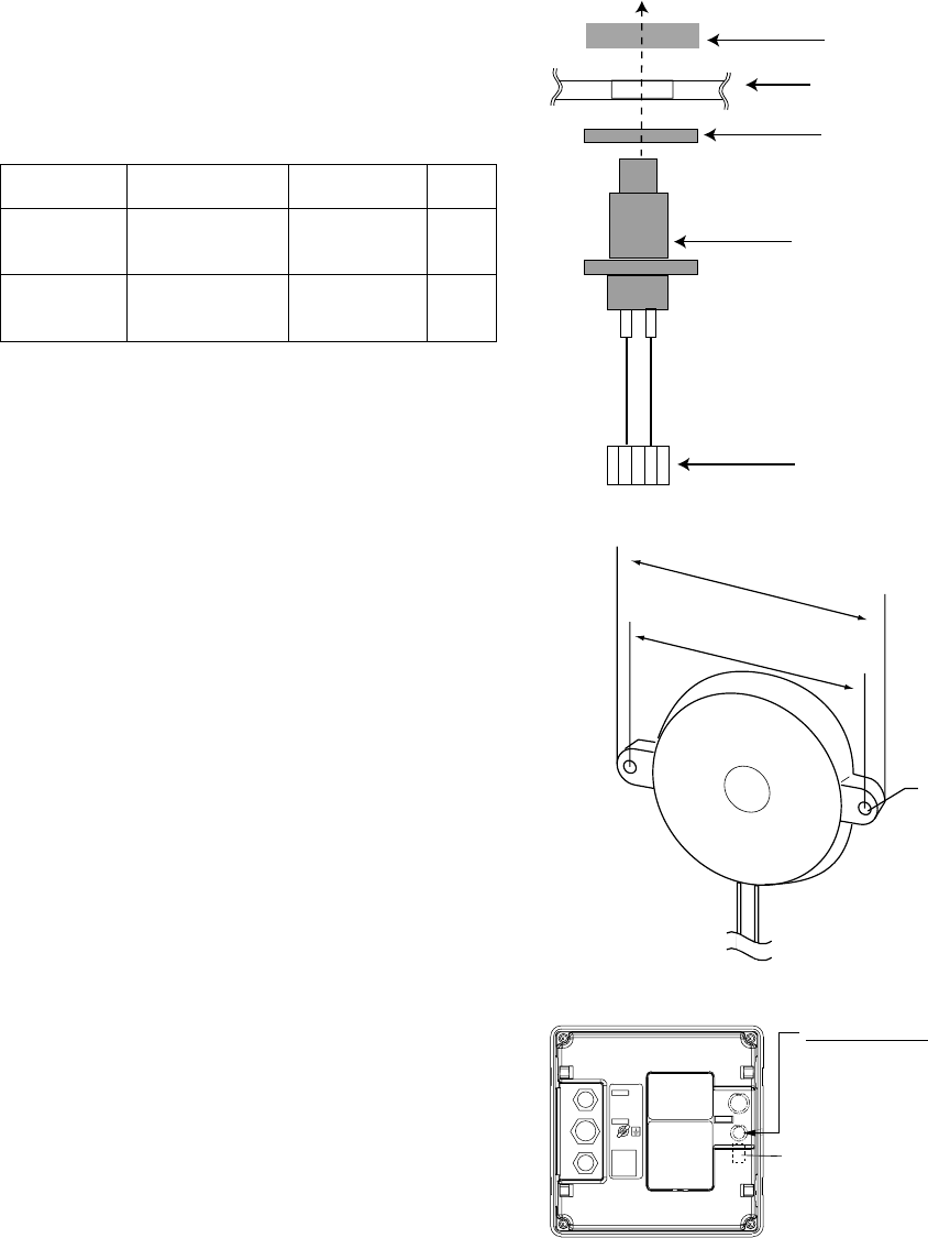
Connector nut
Display unit, rear cover
Connector gasket
MJ connector
XH connector
(to J6 on the DU Board)
Figure 17 Fixing MJ-XH connector assembly
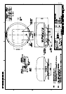
60 mm
50 mm
2-φ3.5
Figure 18 External buzzer
J6 located at right
side of shield case
under the rear panel.
External Buzzer
Remove hole cover with Phillips
screwdriver and hammer.
Remove burrs from hole with
fine file or sandpaper. Attach
connector (supplied as option).
Figure 19 Display unit, rear view