


3
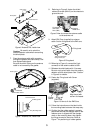
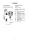
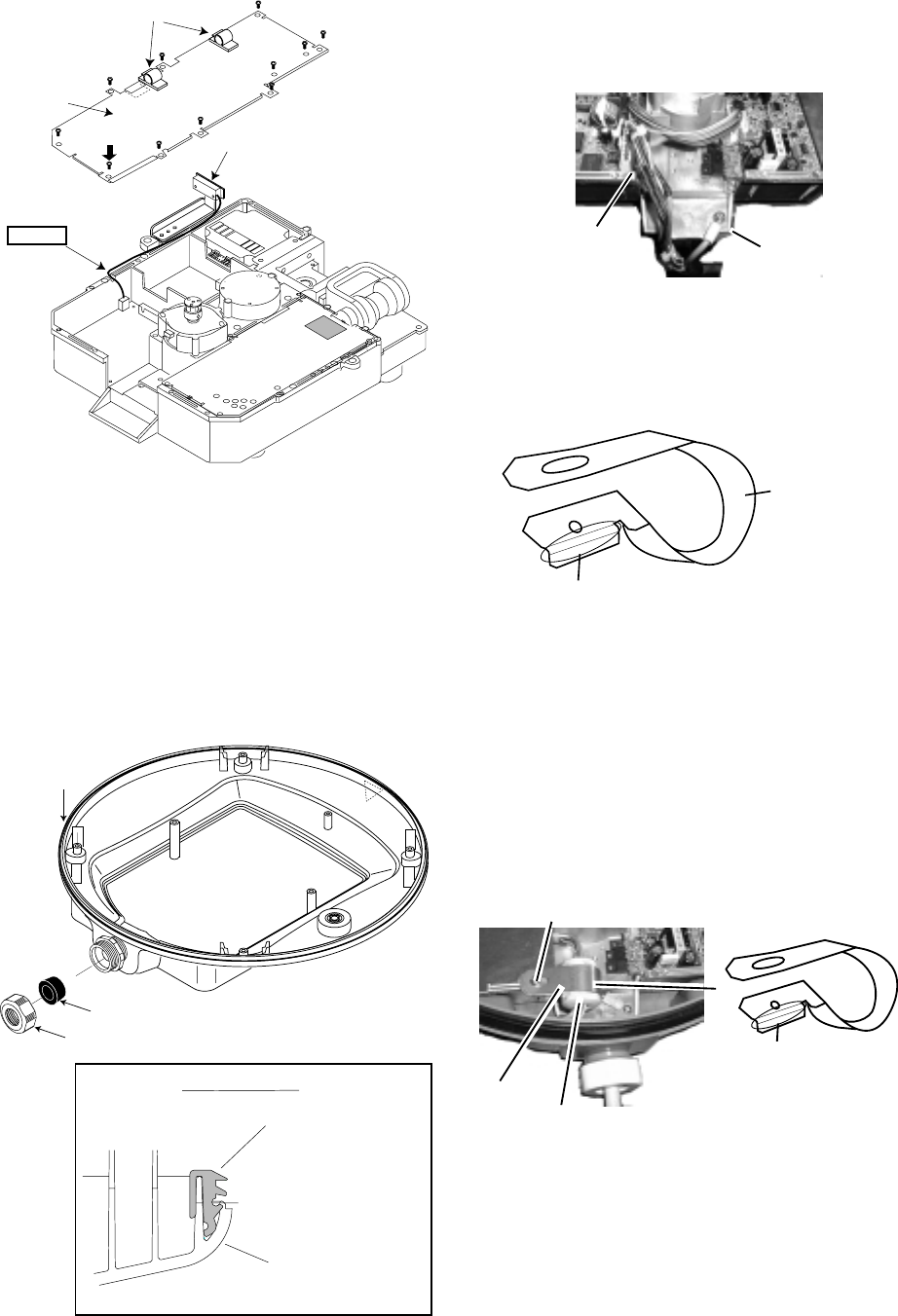
Caution
Cable clamp
Rotation detector
Shield plate
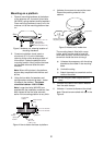
Figure 6 Antenna unit, inside view
Caution:
Be careful not to pinch the
rotation detector cable when remounting
the shield plate.
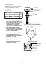
7. Pass the antenna cable with connector
through the gasket and cable clamp, and
then tighten cable gland.
Be sure the shrink tubing on the antenna
cable is not covered by the gasket.
Rubber gasket
Gasket
Cable Gland
Sectional view
Mounting base
Rubber gasket
Figure 7 Antenna unit, inside view
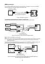
8. Referring to Figure 8, fasten the shield
cable with screw (M4x10) on the chassis to
ground the unit.
Connect 9 pin
connector
here (J801).
Connect
shield here.
Figure 8 How to connect the antenna cable
to the antenna unit
9. Attach EMI Core (supplied) to antenna
cable. Set the fixing band to the EMI core.
This bend should be
facing toward you.
Fixing band
Figure 9 Fixing band
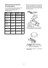
10. Referring to Figure 8, connect the 9-pin
connector of the antenna cable to J801.
11. Refasten the shield plate with 10 screws.
Be sure not to pinch cable from the rotation
detector with the shield plate. See “Caution”
in Figure 6 for details.
12. Fasten the Fixing band with Screw
(supplied).
Screw(M4X15)
EMI Core
Fixing
Band
Align bend with
corner of chassis.
Figure 10 How to fix the EMI Core
13. Follow the instructions on the label inside
the mounting base to secure the snap assy.
14. Confirm that the rubber gasket is properly
positioned and that the triangle mark on the
radome cover is aligned with the triangle
mark on the mounting base, then tighten
the fixing screws for the cover. Refer to
Figure 7 for positioning of rubber gasket.