


2-1
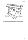
2. WIRING
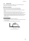
Wiring consideration
• To lessen the chance of picking up electrical interference, avoid where possible routing
the signal cable near other onboard electrical equipment (radars, transmitting radio
antennas, etc.) Also avoid running the cable in parallel with power cables. When crossing
with other cable, the angle should be 90°to minimize the magnetic field coupling.
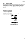
• The signal cable run between the antenna and processor units is available in lengths of
15 m (standard), 30 m and 50 m. Whatever length is used it must be unbroken; namely,
no splicing allowed. Use the signal cable as short as possible to minimize attenuation of
the signal.
• The radar should be connected to an emergency power source, as required by SOLAS
II-1.
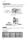
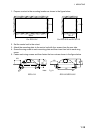
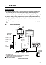
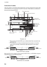
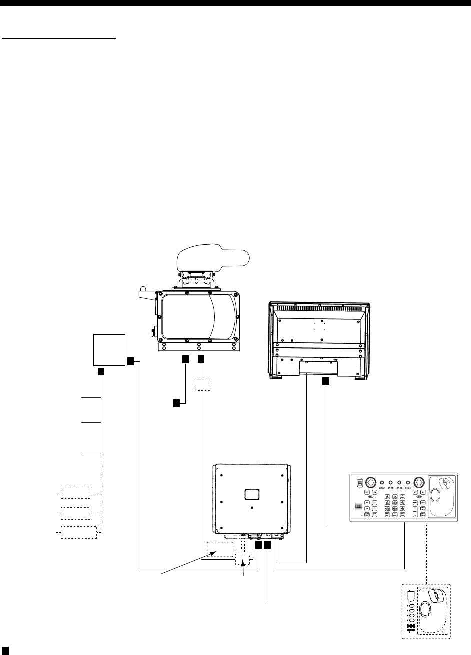
2.1 Interconnection
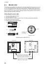
Processor unit
: Cable requires fabrication
100-115 VAC/220-230 VAC
Antenna unit
TB801
TB802
Monitor unit
Control unit
RW-9600
15/30/40/50 m
(Max.100 m)
DPYC-2.5
DPYC-2.5
XH10P-W-6P L=1.5/10/20/30 m
100-230 VAC
DVI-D/D SINGLELINK, 5 m/10 m
110 VAC, 3φ,
60 Hz
220 VAC, 3φ,
50 Hz
440 VAC, 3φ,
50 Hz
For HSC
220 VAC, 3φ, 50 Hz
220 VAC, 3φ, 60 Hz
440 VAC, 3φ, 60 Hz
440 VAC, 3φ, 60 Hz
380 VAC, 3φ, 50 Hz
220 VAC, 3φ, 60 Hz
200 VAC, 3φ, 50 Hz
POWER SUPPLY
UNIT PSU-007
RU-6522
RU-5693
RU-5466-1
Control unit
(RCU-016)
XH10P-W-5P-A
L=10/20/30m
F4
F3
F2
F1
TPYCY-2.5
TPYCY-2.5
(RCU-014 or RCU-015)
Memory card I/F unit
CU-200-FAR
*
*
*
*: Not available for HSC
DPYC-1.5
Junction Box
RJB-001**
Junction Box
RJB-001**
**: If the length of the antenna cable is more than 100m, use Junction box
RJB-001. However, the maximum length is 300m.
Standard Interconnection