


4. INSTALLING OPTIONAL EQUIPMENT
4-4
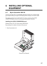
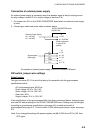
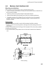
5. Confirm gyrocompass specifications and set up the DIP switches and jumper wires on
the GYRO CONVERTER board according to gyrocompass connected:
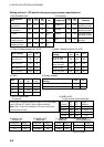
• Setting jumper wires and DIP switches by gyrocompass specifications: page 4-5
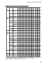
• Setting jumper wires and DIP switches by make and model of gyrocompass: page 4-7
• Location of jumper wires and DIP switches: page 4-8
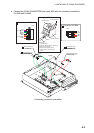
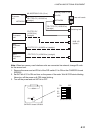
6. Pass gyrocompass cable through the cable clamp and connect it to connector J602 as
shown in the figure on page 4-3.
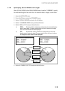
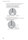
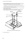
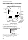
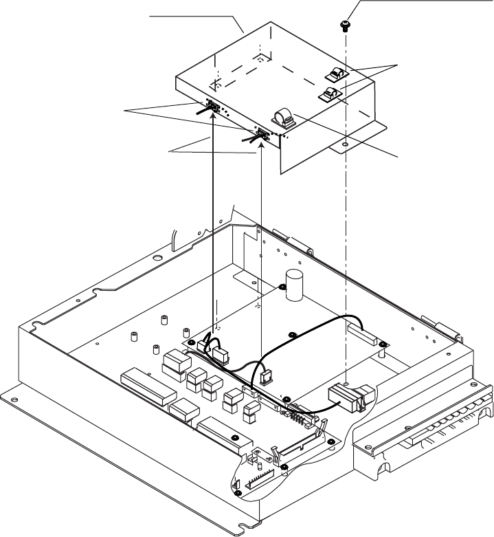
7. Attach the clamps on the plastic cover and then attach the cover to the chassis as
shown in the figure below. Insert cables to the clamp ED-1, respectively.
1
1
4
1
12
1
3
1
2
1
3
1
12
1
5
1
7
1
3
Screw M4X8
3 pcs
(Torque 0.98Nm)
Plastic cover
Insert cables to these
clamp.
Clamp EDS-1
Clamp CKS-10-L
Clamp CKS-13-L
Attaching plastic cover for GYRO CONVERTER board
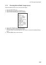
8. Close the processor unit.