


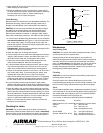

Figure 2. Headroom required on stepped transom
TM258: 244mm (9-3/4")
headroom
Type of Boat
• Single drive—Mount a minimum of 15cm (6") beyond the
swing radius of the propeller (see Figure 1).
• Twin drive—Mount between the drives a minimum of 15cm
(6") beyond the swing radius of the propeller.
• Trim tabs—Mount inside the trim tab, space permitting.
• Stepped transom—Mount the transducer on the lowest step
being sure there is enough headroom for the bracket to release
(see Figure 2).
Installation
WARNING: Always wear safety goggles and a dust mask.
Assembling the Transducer & Bracket
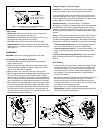
1. Thread the cable through the large hole in the transducer
support (see Figure 3).
2. Fasten the support to the transducer using the three socket-
head-cap screws and washers supplied. Tighten the screws
with the 3/16" Allen wrench supplied.
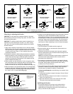
3. Attach a safety ring to one end of each pin (see Figure 4).
4. While holding the transducer assembly against the bracket, insert
a pin through the upper hole in the bracket and the support.
Slide the spacer onto the pin and push it through the remaining
hole in the support and the bracket. Attach a second safety ring.
This pin will function as a hinge when the transducer is released.
5. Slide a washer onto the remaining pin. Push it through the lower
hole in the bracket, slide it along the channel in the support, and
through the second hole in the bracket. Slide the second washer
onto the free end of the pin and attach the second safety ring.
This will function as the locking pin to hold the transducer in the
operational position when underway.
Compensating for Transom Angle
CAUTION: Do not position the leading edge of the transducer
deeper in the water than the trailing edge to avoid aeration.
For the best performance, the transducer beam must be aimed
straight at the bottom (see Figure 5). Since the transom of most
boats is angled, the bracket must compensate for it. Measure the
transom angle of the boat with an angle finder.
Standard transom (12° transom angle)—The bracket is
designed for a standard 12° transom angle. No shim is needed for
this installation. If your boat is capable of speeds above 20kn
(28MPH), install the bracket with one 3° shim, taper down. This
will ensure that the transducer is in contact with the water at high
speeds.
Shims—The bracket is supplied with three shims; each one has a
3° angle. Up to three shims can be combined for a maximum of 9°.
The shims are designed to mate together. Two bosses on the face fit
into recesses in the back of another shim or the holes in the bracket.
•Transom angles greater than 12°—Add the appropriate num-
ber of shims with the taper up to the 12° bracket angle.
• Transom angles less than 12°—To reduce the bracket’s 12°
angle, group the appropriate number of shims with the taper
down.
If you are unsure about using the shim(s), experiment with the
them by following the instructions “Mounting & Adjusting the
Bracket.”
Hole Drilling
1. At the selected mounting location, position the assembly so the
transducer projects 3mm (1/8") below the bottom edge of the
transom (see Figure 1). Be sure any shim(s) is in place. (You
may want to tape the shim(s) to the bracket temporarily.) With
the transducer in the operational position, mark the bottom
corners of the bracket.
2. Remove the transducer assembly from the bracket by removing
the locking pin and the hinge pin (see Figure 4). Hold the
bracket with any shim(s) in place against the transom at the
marked location. Draw an “X” at 12mm (1/2") from the top and
the bottom of each slot (see Figure 6).
3. Using a 5mm, #4, or 7/32" drill bit, drill the four holes.
Fiberglass hull—Minimize surface cracking by running the drill in
reverse until the gelcoat is penetrated.
2
Figure 3. Assembling the transducer
Copyright © 2009 Airmar Technology Corp.
Copyright © 2009 Airmar Technology Corp.
TM260: 260mm (10-1/4")
TM270W: 260mm (10-1/4")
bracket
support
transducer
hinge
locking
spacer
safety
Copyright © 2009 Airmar Technology Corp.
Figure 4. Attaching the transducer to the bracket
screw (3)
washer (3)
support
transducer
cable
washer (2)
pin
pin
ring (4)
detail
channel