


4
Copyright © 2009 Airmar Technology Corp. All rights reserved.
2. Apply sealant to the threads of the remaining screw to prevent
water seeping into the transom.
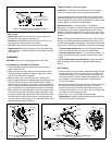
3. Fasten the stabilizing screw into place with a socket wrench.
For clear access to the screw, remove the transducer assembly
from the bracket (see Figure 4). When reattaching the
transducer, be sure to include the spacer.
Cable Routing
Route the cable over the transom for a detachable installation. For
permanent mounting, route the cable through a drain hole or
through a new hole drilled in the transom above the waterline.
CAUTION: Do not remove the connector to ease cable routing. If
the cable must be cut and spliced, use Airmar’s splash-proof
Junction Box No. 33-035 and follow the instructions provided.
Removing the waterproof connector or cutting the cable, except
when using a water-tight junction box, will void the sensor warranty.
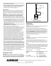
1. If a hole must be drilled through the transom,
choose a location
well above the waterline (see Figure 7). Check for obstructions
such as trim tabs, pumps, or wiring inside the hull. Mark the
location with a pencil. Drill the hole using the appropriate size bit
to
accommodate the connector.
Fiberglass hull—Minimize surface cracking by running the drill in
reverse until the gelcoat is penetrated.
2. Route the cable over or through the transom.
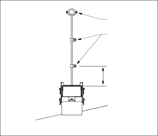
3. On the outside of the hull, secure the cable against the transom
using the cable clamps. Position one cable clamp 30cm (12")
above the bracket. Mark the mounting hole with a pencil.
4. Position the second cable clamp halfway between the first
clamp and the cable hole. Mark this mounting hole.
5. If a hole has been drilled through the transom, open the large
slot in the transom cable cover. Position the cover over the
cable where it enters the hull. Mark the two mounting holes.
6. At each of the marked locations, use a 3mm or 1/8" bit to drill a
hole 10mm (3/8") deep. To prevent drilling too deeply, wrap
masking tape around the bit 10mm (3/8") from the point.
7. Apply marine sealant to the threads of the #6 x 1/2" self-tapping
screw to prevent water from seeping into the transom. Position
the two cable clamps over the cable and fasten them in place.
8. If you have drilled a hole through the transom, apply marine
sealant to the space around the cable where it passes through the
transom. Push the cable cover over the cable and screw it in place.
9. Route the cable to the instrument being careful not to tear the
cable jacket when passing it through the bulkhead(s) and other
parts of the boat. Use grommets to prevent chafing. To reduce
electrical interference, separate the transducer cable from other
electrical wiring and the engine(s). Coil any excess cable and
secure it in place with cable ties to prevent damage.
10.Refer to your echosounder owner’s manual to connect the
transducer to the instrument.
Checking for Leaks
WARNING: Do not leave the boat in the water unchecked for
several days. When the boat is placed in the water, immediately
check for leaks around the screws and any other holes drilled in
the hull. Note that very small leaks may not be readily observed.
Maintenance
Anti-fouling Paint
CAUTION: Do not paint the exposed temperature button. Doing
so will slow the sensor’s response time.
Aquatic growth can accumulate rapidly on the transducer’s
surface reducing performance within weeks. Surfaces exposed to
salt water that do not interlock must be coated with anti-fouling
paint. Use water-based anti-fouling paint only. Never use ketone-
based paint, since ketones can attack many types of plastic
possibly damaging the transducer. Repaint every 6 months or at
the beginning of each boating season.
Cleaning
CAUTION: Do not use a lubricant on the bracket; grit will stick to it
increasing friction and wear.
Clean the sensor with a Scotch-Brite® scour pad and mild
household detergent taking care to avoid making scratches. If the
fouling is severe, lightly wet sand with fine grade wet/dry paper.
Parts
The information needed to order a replacement transducer is printed
on the cable tag. Do not remove this tag. When ordering, specify the
part number, date, and frequency in kHz. For convenient reference,
record this information on the top of page one.
Lost, broken, or warn parts should be replaced immediately.
Bracket Assembly 33-749-01
Obtain parts from your instrument manufacturer or marine dealer.
Gemeco Tel: 843.210.7000
(USA) Fax: 843.210.7170
email: sales@gemeco.com
Airmar EMEA Tel: +33.(0)2.23.52.06.48
(Europe, Middle East, Africa) Fax: +33.(0)2.23.52.06.49
email: sales@airmar-emea.com
AIRMAR
®
TECHNOLOGY CORPORATION
35 Meadowbrook Drive, Milford, New Hampshire 03055-4613, USA
■ www.airmar.com
Figure 7. Cable routing
30cm (12")
cable cover
cable clamp
Copyright © 2009 Airmar Technology Corp.