


5
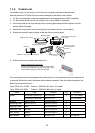
1.1.4 Control unit
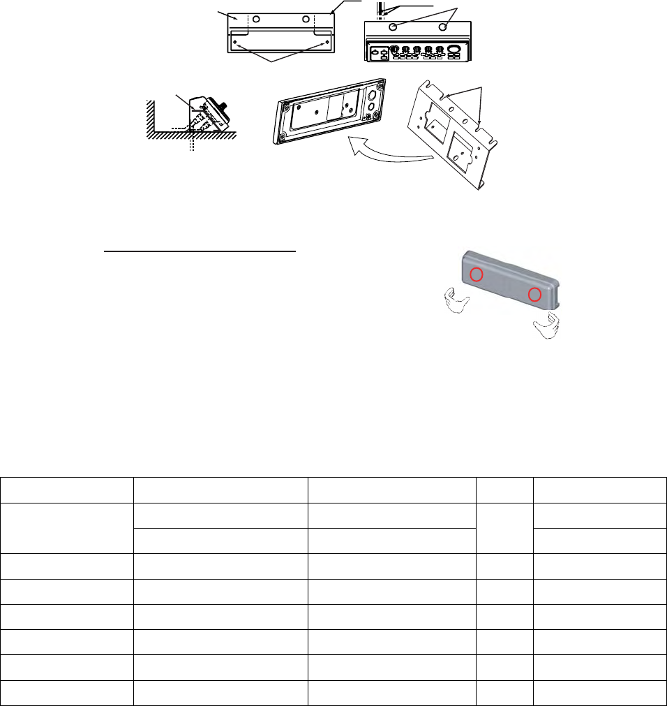
On blackbox type, fix the control unit to the mounting plate (supplied as accessories).
See the parts list of FP06-01120 and outline drawings at the back of this manual.
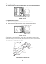
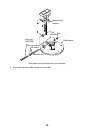
1. Fix the mounting plate to the place selected with two tapping screws (5x20, supplied).
2. Fix the bracket to the control unit with two hex. screws (M4x12, supplied).
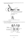
3. Insert the screw driver from the top of the mounting plate holes and then tighten two hex.
screws (M4x12) loosely.
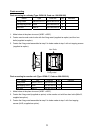
4. Attach the control unit to the mounting plate, and fasten two hex. screws tightly.
5. Attach two cosmetic caps to holes at the top of the mounting plate.
Cable entrance hole
Mounting plate
Cable
Tapping screws (5x20)
Fasten the screws to fix
the bracket.
Bracket
Bracket
Insert to the hex.
screws tightened
at step 3.
Cable can be passed this direction.
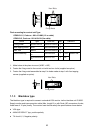
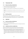
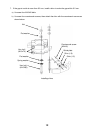
6. Attach hard cover to protect the control unit.
How to remove the hard cover
Place your thumbs at the locations shown with
circles in the illustration at right, and then lift the
cover while pressing it with your thumbs.
On mounting the control unit separate from the monitor unit, the optional control unit separate kit
is required. Mount the control unit same as the above procedure. See the outline drawing at the
back of this manual to mount.
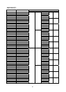
Type: OP06-15-1.5 NEW Code no.: 006-559-140: with 1.5 m cable
Type: OP06-15-5 NEW Code no.: 006-559-150: with 5 m cable
Name Type Code no. Qty Remarks
MJ-A10SPF0002-015 000-142-878 For 1.5 m cable Cable
MJ-A10SPF0002-050 000-131-411
1
For 5 m cable
Bracket 06-021-2112 100-281-880-10 1
Mounting Plate 06-021-2111-1 100-279-741-10 1
Tapping Screw 5x20 000-162-608-10 2
Cosmetic Cap DP-687 000-165-997-10 2
Hex. Screw M4x12 000-162-939-10 4
Bind Screw M4x10 000-807-331 4 For monitor