


ii
TABLE OF CONTENTS
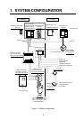
1. SYSTEM CONFIGURATION ............................................................................ 1
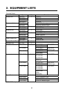
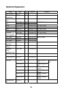
2. EQUIPMENT LISTS .......................................................................................... 2
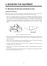
3. MOUNTING THE EQUIPMENT
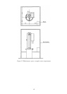
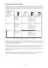
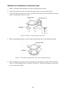
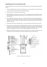
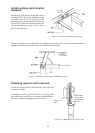
3.1 Mounting the Hull Unit and Receiver Unit ........................................................................3
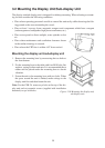
3.2 Mounting the Display Unit/Sub-display Unit .....................................................................9
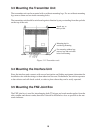
3.3 Mounting the Transmitter Unit........................................................................................10
3.4 Mounting the Interface Unit............................................................................................10
3.5 Mounting the FNZ Joint Box ..........................................................................................10
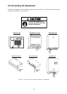
3.6 Grounding the Equipment ............................................................................................11
4. WIRING
4.1 Cable Configuration.......................................................................................................12
4.2 How to Use the Crimping Tool, Pin Extractor.................................................................13
4.3 Location of Connectors ................................................................................................14
4.4 Fabricating Cables, Assembling Connectors .................................................................15
4.5 Connection of Transducer Cables..................................................................................23
4.6 Connection of Interface Unit CS-120A .........................................................................24
4.7 Connection of Sub-display Unit CSH-236/236F (Option) ...............................................29
4.8 Synchronizing Transmission with Other Sonars, Echo Sounders...................................30
4.9 Interlocking Operation with Other Sonar ........................................................................32
5. CHANGING POWER SPECIFICATIONS ...................................................... 34
6. ADJUSTMENT AND CHECK
6.1 Hull Unit Check..............................................................................................................35
6.2 Heading Adjustment ......................................................................................................36
6.3 DIP Switch Setting in the Display Unit ...........................................................................37
6.4 Setting and Adjustment of the Interface Unit CS-120A...................................................38
7. PROCESSOR UNIT CSH-235/235F ............................................................... 42
SPARE PARTS/INSTALLATION MATERIALS/ACCESSORIES .................... A-1
OUTLINE DRAWINGS ...................................................................................... D-1
INTERCONNECTON DIAGRAMS .....................................................................S-1