


35
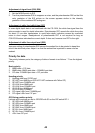
6. ADJUSTMENT AND CHECK
6.1 Hull Unit Check
1. Press the ON switch to turn on the equipment. Con-
firm that the lamps above the ON and c switches
light.
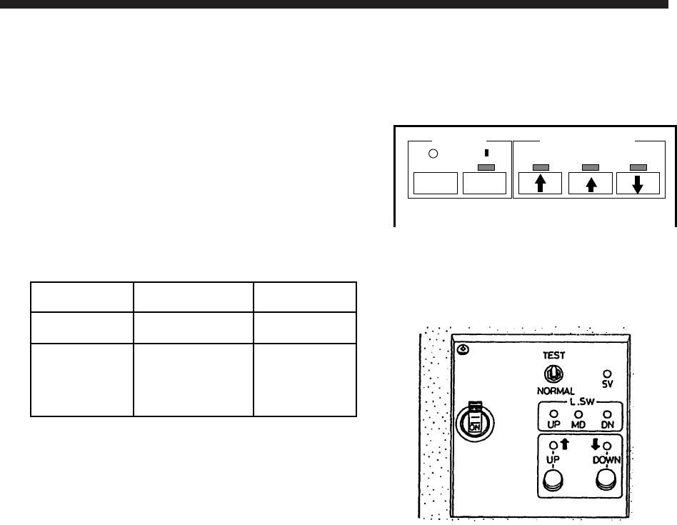
2. Confirm that the 5V and UP lamps on the raise/
lower control box are lit.
3. Remove the cover of the raise/lower control box
and check the following voltages:
Terminal Terminal No. Voltage
TB-D1 7 – 8 +12 V
TB-D2
1 – 2
2 – 3
1 – 3
180 VAC
180 VAC
360 VAC
4. In the raise/lower control box, turn the TEST/NOR-
MAL switch to TEST. Press the d switch to con-
firm that the transducer lowers. Also, while the
transducer is being lowered, check that the MD LED
lights when the MD L. SW kicks. Note that the MD
L. SW does not stop the transducer when the TEST/
NORMAL switch is in the TEST position.
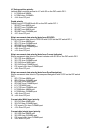
5. Press and release the d switch. Confirm that the transducer stops at the moment the switch
is released.
6. Press the d switch again. Confirm that the transducer stops at the moment the lower limit
switch kicks.
7. Confirm that the c switch operates in a similar manner.
8. Check that LEDs on the panel of the raise/lower control box light as follows:
1) UP, MD and DN LEDs light when corresponding limit switch kicks.
2) UP and DOWN LEDs light while UP and DOWN switches are pressed and extinguish
when switches are released.
9. Set the TEST/NORMAL switch to NORMAL.
10. At the display unit, press the d (mid position) switch. Confirm that the lamp above the
switch blinks while the transducer is being lowered, a short beep sounds when the mid limit
switch kicks, and the lamp lights when the transducer is fully lowered.
11. Press the d switch. Confirm that the lamp above the switch blinks while the transducer is
being lowered, a short beep sounds when the mid limit switch kicks, and the lamp lights
when the transducer is fully lowered.
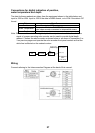
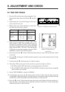
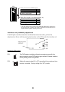
POWER
TRANSDUCER
OFF ON
Figure 6-1 Display unit front panel
Figure 6-2 Raise/Lower
control box