


2-6
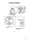
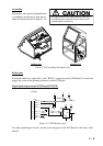
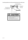
When the De-Icer is installed
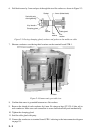
1) Before beginning any work on the scanner unit, turn off both the DE-ICER switch (S31) on
the sub panel of the display unit and the breaker for the de-icer line at the main switchboard
to remove the power (100 VAC, 1ø) to the de-icer. (Turning off the power to the display unit
has no effect.)
2) The neck of the scanner unit becomes VERY HOT when the de-icer is working. (The de-
icer turns on when ambient temperature is below 0°C.)
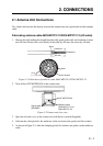
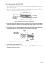
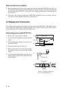
2.2 Display Unit Connection
Two cables are terminated at the display unit: the signal cable RW-4839 or RW-6895 and the
power cable. The signal cable, available in lengths of 15m, 20m, or 30m, comes with a connec-
tor preattached to it for connection to the display unit.
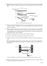
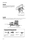
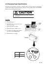
Figure 2-11 How to fabricate
power cable DPYCY-3.5
15 mm
Clamp here
Taping
(a)
(b)
(d)
Vinyl jacket
Armor
DPYCY-3.5
5 mm
Terminal cap
(c)
10 mm
Approx. 150 mm
Fabricating power cable DPYCY-3.5
1) Remove the vinyl jacket by 150mm.
2) Cut off jute tape wrapped around the braided
shield.
3) Unravel the braided shield to expose the cores
by about 120mm.
4) Slip the terminal cap onto the core.
5) Remove insulation of cores by about 10mm.
Fix crimp-on lugs to the cores and braided
shield.
6) Cover the braided shield with vinyl tape, leav-
ing the portion which will lie inside the cable
clamp untaped.