


3-2
000
010
020
030
040
050
060
070
080
090
100
110
120
130
140
150
160
170
180
190
200
210
220
230
240
250
260
270
280
290
300
310
320
330
340
350
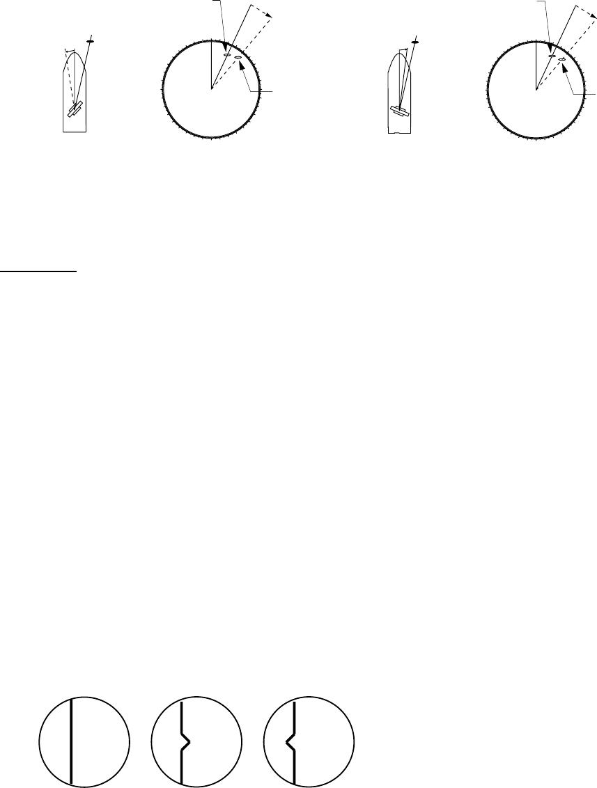
β
Target
β
Apparent position
of target
Antenna mounted error
to starboard (heading
switch delayed)
Picture appears
deviated counterclockwise.
Correct
bearing
relative to
heading
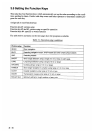
6) Press the [2] key several times to select OTHER S-BAND.
7) Press the [ENTER] key.
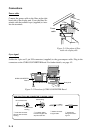
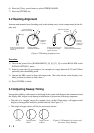
3.2 Heading Alignment
Antenna unit mounted error (heading reed switch timing error) can be compensated at the dis-
play unit.
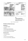
Figure 3-2 Heading alignment error
Procedure
1) Turn on the power. Press [RADAR MENU] [0] [0] [2] [2] to select HD ALIGN on the
INITIAL SETTING 1 menu.
2) Select a target echo (by gyrocompass, for example) at a range between 0.125 and 0.25nm,
preferably near the heading mark.
3) Operate the EBL control to bisect the target echo. (The value shown on the display is an-
tenna position in relation to ship's bow.)
4) Press [ENTER] to finish.
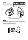
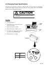
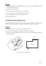
3.3 Adjusting Sweep Timing
Sweep timing differs with respect to the length of the signal cable between the antenna unit and
the display unit. Adjust sweep timing at installation to prevent the following symptoms:
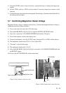
• The echo of a "straight" target (for example, pier), on the 0.25nm range, will appear on the
display as being pulled inward or pushed outward. See Figure 3-3.
• The range of target echoes will also be incorrectly shown.
000
010
020
030
040
050
060
070
080
090
100
110
120
130
140
150
160
170
180
190
200
210
220
230
240
250
260
270
280
290
300
310
320
330
340
350
α
Target
α
Correct bearing
relative to heading
Antenna mounted error
to port (heading switch
advance)
Picture appears
deviated clockwise.
Apparent
position
of target
Correct Target pushed Target pushed
inward outward
Figure 3-3 Examples of correct and
incorrect sweep timings