


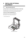
4. INSTALLING OPTIONAL EQUIPMENT
4-5
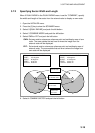
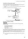
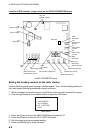
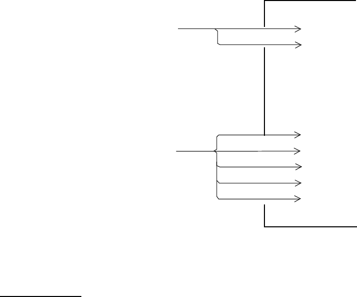
Connection of external power supply
An external power supply is necessary when the repeater signal is step-by-step type and
the step voltage is below 20 V or output voltage is less than 5 W.
1. Cut jumper wire JP1 on the GYRO CONVERTER board when an external power supply
is used.
2. Connect gyro cable and power cable as shown below.
GYRO CONVERTER board
[A] 64P1106
1 > R2
Either connection
in case of DC
polarity.
J5
2 > R1/COM
External Power Supply
20 - 135 VAC
20 - 100 VDC
1 > S1
2 > S2
3 > S3
4 > T
5 > F.G.
Gyrocompass
(Step type)
S1
S2
S3
COM
F.G.
J4
Connection of external power supply to GYRO CONVERTER board
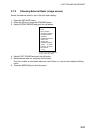
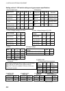
DIP switch, jumper wire settings
Default setting
The gyro converter GC-10 is set at the factory for connection with the gyrocompass
specifications below.
AC synchronous signal: 50/60 Hz
Rotor voltage: 60 V to 135 V AC
Stator voltage: 60 V to 135 V AC
Gear ratio: 360x
Supply voltage: 30 V to 135 V AC
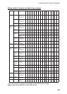
If the specifications of the gyrocompass differ from those mentioned above, change jumper
wire and DIP switch settings on the GYRO CONVERTER board. Settings may be changed
according to gyrocompass specifications (see page 4-6) or make and model of
gyrocompass (see page 4-7). For the location of DIP switches and jumper wires, see page
4-8.
Note: If you change the setting with power supplied, set #8 of SW2 from OFF to ON, then
OFF again.