


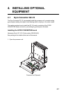

4. INSTALLING OPTIONAL EQUIPMENT
4-8
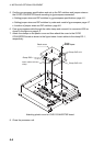
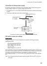
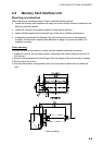
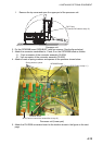
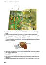
Location of DIP switches, jumper wires on the GYRO CONVERTER board
64P1106
JP5, JP4
(Supply voltage)
JP2
(Stator voltage)
JP3
(Rotor voltage)
JP1
(Gyro type)
Fuse
(2A)
J5
(Rotor signal input,
external power input)
J4
(Stator signal input)
SW1
DIP switch
J6
(IEC-61162-1 output port)
J7
(Data output port #1)
J8
(Data output port #2)
J9
(Data output port #3)
JP6, JP7
(AD format
data Tx interval)
SW2
DIP switch
J10
(Data output
port #4)
J11
(Data output
port #5)
J12
(Data output
port #6)
SW3
DIP switch
GYRO CONVERTER board
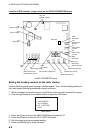
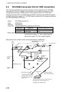
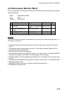
Setting the heading readout on the radar display
Confirm that the gyrocompass is giving a reliable readout. Then, set the heading readout on
the radar display with the gyrocompass readout as follows:
1. Roll the trackball to place the arrow in the HDG box at the top right corner of the screen.
2. Push the right button on the trackball module to open the HDG menu.
[HDG MENU]
1 HDG SOURCE
AD-10/SERIAL
2 GC-10 SETTING
000.0˚
HDG menu
3. Press the [1] key to choose the HDG SOURCE and choose AD-10.
4. Press the [2] key to choose the GC-10 SETTING option.
5. Roll the wheel to set gyrocompass reading.
6. Press the [MENU] key to close the menu.