


2-10
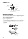
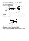
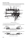
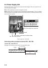
Connection of cables
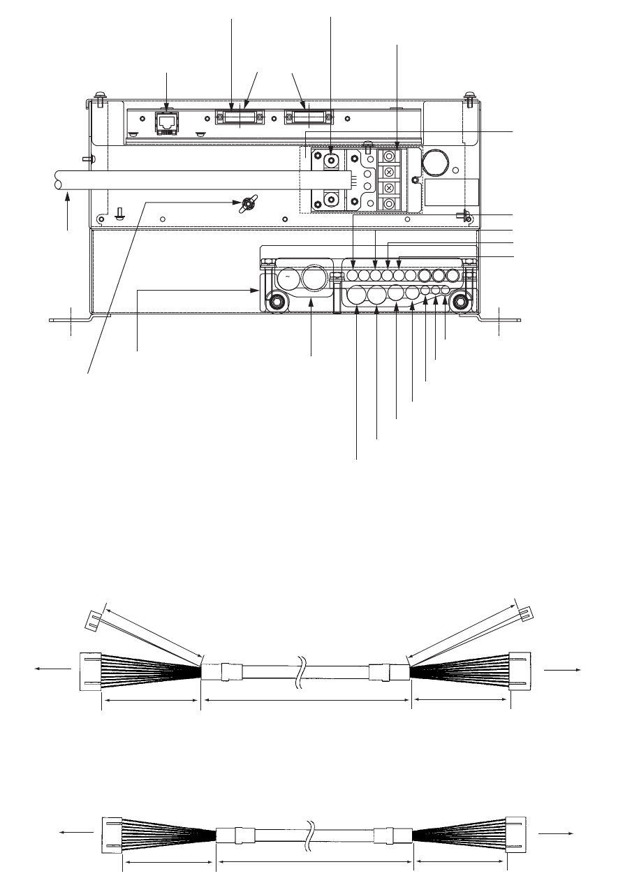
The power cable is connected to the terminal board on the rear panel and the signal cable from
the monitor unit is connected to the DVI-D connector. Other cables are connected to the printed
circuit board 03P9342. Be sure to ground the unit, with IV-8sq wire (local supply).
Processor unit, rear view
*: The connector with EMI core should be connected to the processor unit.
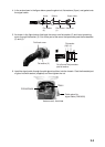
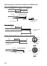
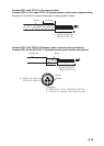
**: The configuration of optional cable between the processor unit and the control unit is as follows.
Note that the cable fabrication for each end is different.
Cable XH10P-W-6P L=20/30M
When the RCU-016 is installed, optional cable (XH10P-W-5P-A, L=10/20/30M) is required. Cable
fabrication for each end is the same.
Cable XH10P-W-5P-A L=10/20/30M
F1
1
2
ACK
φ18.9
AIS
17
AD100
8
GYRO
28
PSU004
24
φ7.4
VDR IN
φ7
VDR OUT
24'
26
9 14
17
15
DC/AC
21
φ9
HDG
32 54 6
RSD
1918 20
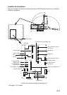
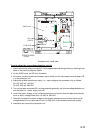
Monitor unit
Network DVI-D monitor
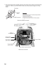
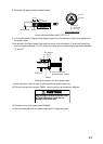
Cable clamp for power cable
Terminal board for power cable
Remove the
protective cover.
Control unit**
Heading senor
Speed log
Navigator
Memory Card IF unit
VDR OUT
VDR IN
Gyrocompass
AD-100
AIS
Antenna unit
Cable clamp
GND TERMINAL
Power cable
*
Power supply unit
FUSE
F70
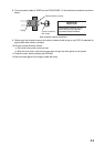
Control unit
Processor unit
10/20
*
/30
*
m
300 mm
150 mm
*: Option
160 mm
350 mm
10/20/30 m
150 mm
150 mm
C
ontrol unit
Processor un
it