


4-13
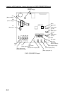
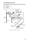
4.3 DVI-RGB Conversion Kit
This information provides the procedure necessary for the installation of the DVI-RGB conversion
kit. This kit is installed in the processor unit to enable connection of an RGB monitor or VDR
(Voyage Data Recorder).
Name: DVI-RGB conversion kit
Type: OP03-180-2
Code no.: 008-536-070
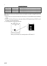
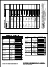
See packing list for contents. Refer to the figure below for modification.
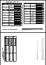
How to wire the DVI-RBG conversion board
M3x8
4 pcs
Spacer
SQ-35
6 pcs
Fixing
holes
Spring washer
Boss
J2
J3
(3 pin)
J1
(13 pin)
J615
J3
J9
(10 pin)
J4
(6 pin)
M3x8
6 pcs
RGB Cable
(User supply)
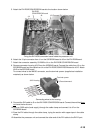
Clamp copper tape
section by cable clamp.
Ferrite core side: Connect to DVI-D port on
the upper part of the processor unit.
DVI cable
03P9342 board
RGB-BUFF board
(03P9229B)
(SLB-FRN4-A)
DVI-RGB CONVERSION board
03-2092
03-2094
03-2093
Ferrite core
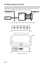
To external monitor or
BNC connector converter
(see page 4-15).
D-sub 15P
Female