


3-2
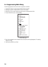
3.2 Heading Alignment
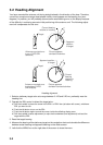
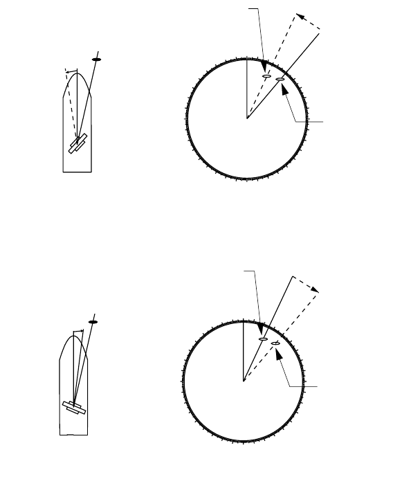
You have mounted the antenna unit facing straight ahead in the direction of the bow. Therefore,
a small but conspicuous target dead ahead visually should appear on the heading line (zero
degrees). In practice, you will probably observe some small bearing error on the display because
of the difficulty in achieving accurate initial positioning of the antenna unit. The following adjust-
ment will compensate for this error.
Heading alignment
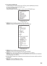
1. Select a stationary target echo at a range between 0.125 and 0.25 nm, preferably near the
heading line.
2. Operate the EBL control to bisect the target echo:
a) Roll the trackball to place the arrow in the EBL1 or EBL2 box (at bottom left corner), whichever
EBL you want to use.
b) Push the left button to turn on the EBL.
c) Push the left button again to send the cursor inside the effective display area.
d) Roll the trackball (coarse adjustment) or spin the thumbwheel (fine adjustment) to bisect the
target with the EBL.
3. Read the target bearing.
4. Measure the bearing of the stationary target on the navigation chart and calculate the difference
between actual bearing and apparent bearing on the radar screen.
5. Left-click the MENU box at the right side of the screen to close the menu.
000
010
020
030
040
050
060
070
080
090
100
110
120
130
140
150
160
170
180
190
200
210
220
230
240
250
260
270
280
290
300
310
320
330
340
350
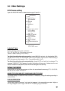
α
Target
α
Correct bearing
relative to heading
Antenna mounted error
to port (HDG SW
advance)
Picture appears
deviated clockwise.
000
010
020
030
040
050
060
070
080
090
100
110
120
130
140
150
160
170
180
190
200
210
220
230
240
250
260
270
280
290
300
310
320
330
340
350
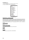
β
Target
β
Apparent position
of target
Antenna mounted error
to starboard (HDG
SW delayed)
Picture appears
deviated counterclockwise.
Correct
bearing
relative to
heading
Apparent
position
of target