


xxi
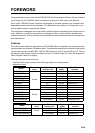
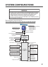
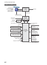
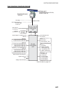
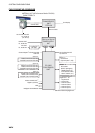
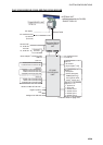
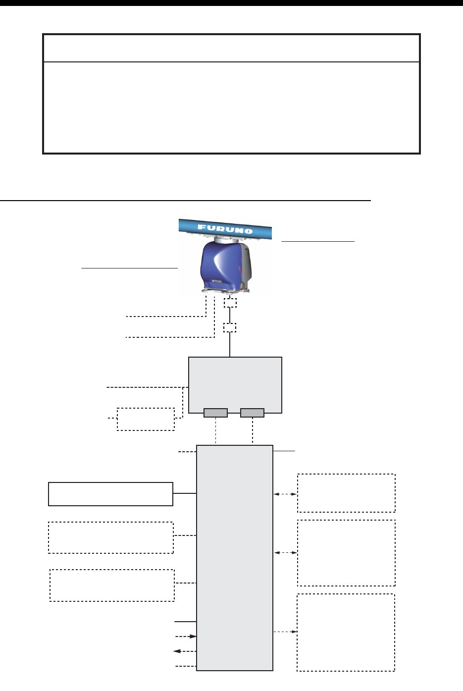
SYSTEM CONFIGURATIONS
Basic configuration is shown with solid line.
FAR-3210/FAR-3220/FAR-3310/FAR-3320/FAR-3210-BB/FAR-3220-BB
NOTICE
The radar(s) must be interconnected to the following type approved sensors:
Gyrocompass meeting the requirements of the IMO resolution A.424(XI).
EPFS meeting the requirements of the IMO resolution MSC.112(73).
SDME meeting the requirements of IMO resolution MSC.96(72).
The radar may be interconnected via HUB-3000 to other FURUNO processing
units having approved LAN ports.
100-115/220-230 VAC
1ø, 50-60 Hz
PSU-014
POWER SUPPLY
UNIT
EC-3000
PROCESSOR
UNIT
Serial 1, 2
IEC 61162-2
(Gyrocompass
*
1
, AIS)
Serial 3 - 7
IEC 61162-1
(EPFS
*
2
(Navigator),
SDME
(Speed Log),
Echo Sounder, Wind,
Alarm
*
5
, Navtex, etc.)
Digital Out 1 - 6*
5
1: System Fail
2: Power Fail
3: Normal Close 1
4: Normal Close 2
5: Normal Open 1
6: Normal Open 2
100-230 VAC
1ø, 50-60 Hz
Transformer
RU-1803
440 VAC
1ø, 50-60 Hz
Sensor Adapter*
4
or Switching HUB
HUB-100
ANTENNA UNIT
(w/Performance Monitor PM-32A)
XN12CF-RSB-128
XN20CF-RSB-128
XN24CF-RSB-128
TRANSCEIVER UNIT
RTR-105 (12 kW)
RTR-106 (25 kW)
Sub display
LAN
Serial
Select one
Select one
Select one
100-115/220-230 VAC
1ø, 50-60 Hz
(for de-icer)
Radar Control Unit RCU-025
Trackball Control Unit RCU-026
ECDIS Control Unit RCU-024
Radar Control Unit RCU-025
Trackball Control Unit RCU-026
ECDIS Control Unit RCU-024
Radar Control Unit RCU-025
Trackball Control Unit RCU-026
Monitor Unit MU-190
*
3
MU-231*
3
Digital In (ACK IN)
VDR
Intelligent Hub HUB-3000
*
: See the notes on page xxvi.
Junction box
*
6
RJB-001
Junction box
*
6
RJB-001