


2-2
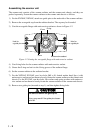
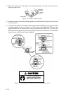
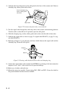
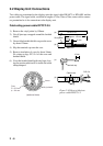
4) Unfasten the four fixing bolts on the cable gland at the base of the scanner unit. Remove
clamping ring, rubber gasket and washers.
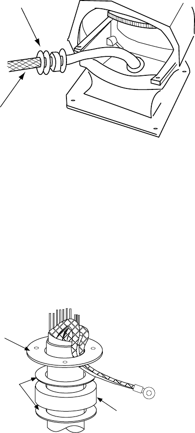
From left: Clamping ring,
washer, rubber gasket
and washer
Signal cable
Figure 2-2 Scanner unit, front view, cover removed
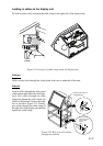
5) Pass the signal cable through the cable entry hole in the scanner unit mounting platform.
Trim the cable so about 80 cm of it protrudes past the cable gland.
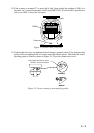
6) Slide the clamping ring, washer, rubber gasket and washer onto the cable in that order.
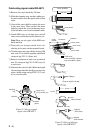
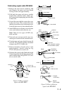
7) Fabricate the signal cable as shown on page 2-4 (signal cable RW-4873), or page 2-5 (sig-
nal cable RW-6875).
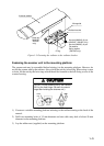
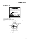
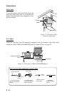
8) Referring to Figure 2-3, pass the outer and inner shields between the signal cable and the
clamping ring. Fasten the cable gland.
Clamping
ring
Washers
Rubber
gasket
Figure 2-3 Passing cable shields between cable and clamping ring
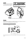
9) Connect the signal cable to the terminal board RTB801 by referring to the interconnection
diagram. Leave “slack” in the coaxial wire to prevent breakage.
10) Bind cores of cables with cable ties.
11) Mount the transceiver module. Connect plugs P611, P801 and P821. Fasten the shield to
the ground terminal on the transceiver module.