


2-13
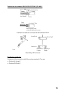
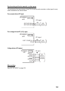
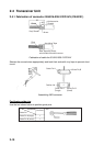
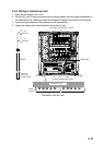
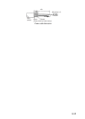
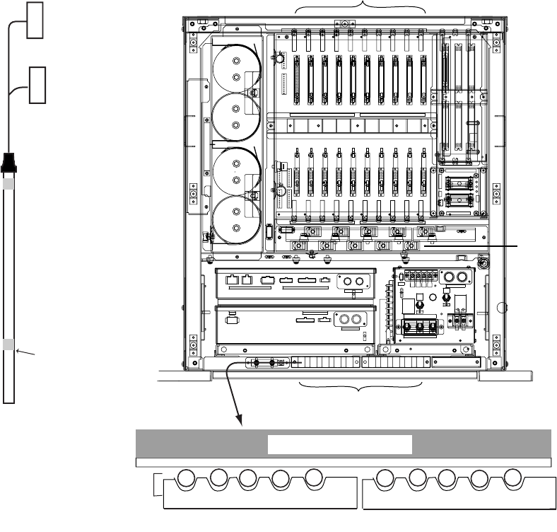
2.4.4 Wiring in transceiver unit
1. Open the transceiver unit cover.
2. Plug the P1 and P2 connectors at the end of signal cables into the proper receptacles in
the transceiver unit, referring to the interconnection diagram at the back of this manual.
3. Lead the signal cables into the transceiver unit appropriately.
4. Fasten the cables with cable clips after wiring the hull unit.
13-L
16-L
05-L
SB-1909
SB-1909
07-L
SM4P
EL4P
SM12P
YL8P
EL3P
SM12PSM8P
EL12P EL9P
SM18P
VH-3P
EDS3
EDS3
EDS3
TB-B101
INPUT
F602
I
MAINTENANCE
Maintenance
I
F601
MAIN
J601
/220/230 VAC
50/60Hz
12
:15A
L
L
S605
L
L
S605
H
S603INPUT(TB-B101)
L100V
H110V
H
S603
S604
H
S604
L
H
H
L
H
L
H220V
L
H230V
HH115V L
(Should be OFF
operation.)
for Normal
Use Only.
100/110/115
15A15A
J303J302J301
5A5A
J206J205J204J201 J202 J203
6962 6963
CN-B202 CN-B201CN-B203CN-B205CN-B206 CN-B204
CN-B208CN-B209CN-B210 CN-B207
TRX-2 TRX-1TRX-3TRX-5TRX-6 TRX-4
TRX-8TRX-9TRX-10 TRX-7
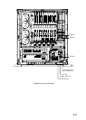
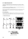
Transceiver unit
10 9 8 7 6 5 4 3 2 1
Cable
number
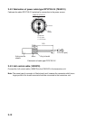
10S2223
Secure
here with
metal clamp.
P2
(40 pin)
P1
(34 pin)
Fix signal cables with clamp.
From right to left B201 to B210
Cable clip
Transceiver unit, top view