


4-2
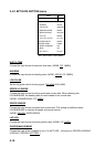
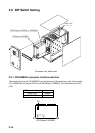
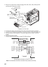
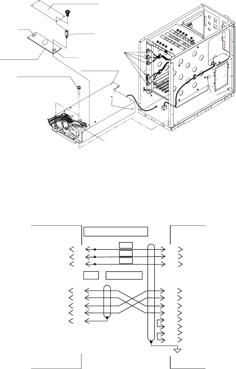
2. Remove two upset screws, detach the plugs J503, J502, J501, J504, J506 and J507,
and then pull out the power module.
IFES
SCAN
SCAN2
DUAL
DCON
Power Module
VH4P
VH5P
Upset screws
M5x25 SUS 2 pcs.
Protection sheet
Power supply
pcb
Spacer
Detach J503, J502,
J501, J504 and
J506.
Detach J507.
Hole
Pin
Processor unit, front view
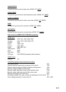
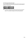
3. Fix the power supply pcb (supplied) to the power module with spacers (supplied).
4. Connect two VH connectors (provided on the power module) to the power supply pcb.
5. Set the protection sheet (supplied) to the power supply pcb and fasten it with four
screws.
6. Reattach the power module.
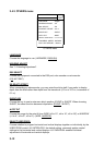
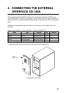
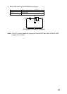
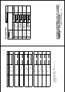
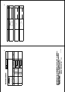
7. Connect between the processor unit and CS-120A as follows.
CS-120A
J201
Processor Unit
YEL BRN
BRN
BRN
POWER FOR CS-120A port
CIF1 or NMEA2/CIF2
port
L
E
PP
1
2
3
NN
MM
JJ
KK
BB
EE
DD
Z
1
2
3
4
10
24V
0V
GND
TD-H
TD-C
RD-H
RD-C
GND
DSR-C
DSR-H
DTR-H
+24V_H
+24V_C
GND
CIF_TXD_H
CIF_TXD_C
CIF_RXD_H
CIF_RXD_C
SHIELD
37-core cable
10S1258
NJC-203-PM
ORG
PPL
Wiring between processor unit and CS-120A
Note: An echosounder should be connected to the processor unit directly.