


2 GPSMAP 700 Series Installation Instructions
Bail Mounting the Chartplotter
Use the included bracket to bail mount the GPSMAP 700 series chartplotter. You can route cables from under the mounting surface through the
included bail-mount bracket, though it is not necessary. See page 3 for instructions on installing the bail-mount bracket without routing cables
through the bracket.
Hardware (included):
• Bail-mount bracket
• Cable-organization bracket
• Bail-mount template
• Four 35 mm M 4.2 × 1.4 screws (to secure the bail-mount bracket )
• Two 20 mm M 3.5 × 1.3 screws (to secure the cable-organization
bracket)
Tools required (not included):
• Jigsaw
• Drill and drill bits—1
1
/
4
in. (32 mm), and
1
/
8
in. (3 mm)
• Number 2 Phillips screwdriver
To install the bail-mount bracket with the cables routed through the bracket:
1. Using the included bail-mount bracket template, determine the best place to install the bracket. Be sure to leave adequate clearance behind
the chartplotter for the wiring.
NOTE: To avoid interference, mount the GPSMAP 700 series chartplotter at least 32 in. (813 mm) from a magnetic compass.
2. The bail-mount bracket template has adhesive on the back. Remove the
protective liner and apply the template to the location at which you want to install
the bail-mount bracket.
3. Use a 1
1
/
4
in. (32 mm) drill bit to drill the pass-through hole in the center of the
template.
4. Use a use a
1
/
8
in. (3 mm) drill bit to drill the six pilot holes marked on the bail-
mount template.
NOTE: If you are mounting the chartplotter in berglass, it is recommended to use
a countersink bit to drill a clearance-counter bore through only the top gel-coat
layer. This will help to avoid any cracking in the gel-coat layer when the screws
are tightened.
5. Remove the bail-mount bracket template from the mounting surface.
6. Route the cables pertinent to your installation through the hole you drilled in step 3,
from under the mounting surface.
If you plan to use all four cables, route them in the following order to ensure that
they will all t correctly:
Radar cable
Power/data wiring cable
GA 30 GPS antenna cable
NMEA 2000 cable
NOTE: Do not install the locking ring (page 4) on the power/data or radar cable until after you route it through the mounting surface.
7. Place the cable-organization bracket around the cables and into the 1
1
/
4
in. (32 mm) hole you drilled in step 3.
8. Use the two included 20 mm M 3.5 × 1.3 screws to secure the cable-organization bracket to the mounting surface.
NOTE: Stainless-steel screws may bind when screwed into berglass and
overtightened. Garmin recommends applying an anti-galling, stainless anti-seize
lubricant to the screw before using.
9. Extend 6–7 in. (152–178 mm) of cable slack through the cable organization bracket, and
secure each cable to the correct clips. Refer to the cable-organization bracket diagram
for the clip assignments.
10. Place the bail-mount bracket over the cable-organization bracket and route the cables
through the back of the bail-mount bracket.
11. Secure the bail mount to the surface using the four included 35 mm M 4.2 × 1.4 screws.
12. Follow the steps on page 3 to install the GPSMAP 700 series chartplotter on the bail
mount bracket. Test the slack-length of the cables routed through the bracket.
13. Make cable slack-length adjustments if necessary. Apply marine sealant (optional).
•
•
•
•
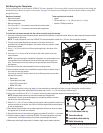
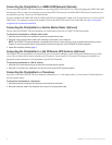
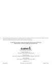
Cable-organization
bracket
Bail-mount
bracket
GPSMAP
700 series
chartplotter
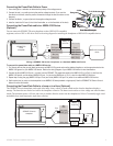
Bail-Mounting the GPSMAP 700 Series Chartplotter
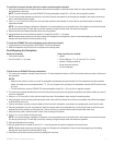
Cable-organization
bracket
Bail-mount
bracket
GPSMAP
700 series
chartplotter
Bail-Mounting the GPSMAP 700 Series Chartplotter
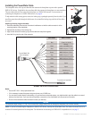
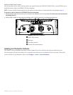
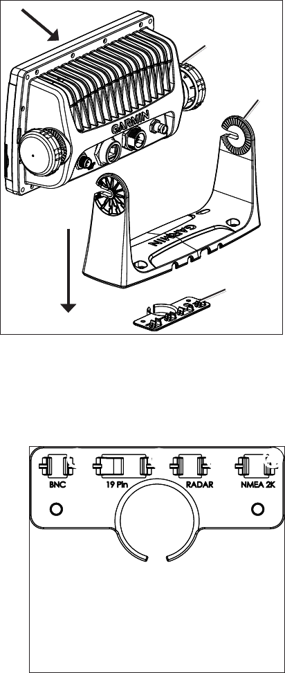
Cable-Organization-Bracket Clip Identication
➊ ➋
➌
➍
➊
GA 30 GPS antenna cable clip
➋
Power/data cable clip
➌
Garmin Marine Radar cable clip
➍
NMEA 2000 cable clip
Cable-Organization-Bracket Clip Identication
➊ ➋
➌
➍
➊
GA 30 GPS antenna cable clip
➋
Power/data cable clip
➌
Garmin Marine Radar cable clip
➍
NMEA 2000 cable clip