


GPSMAP 700 Series Installation Instructions 5
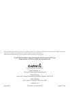
Connecting the Power/Data Cable to Power
1. Use a test light or a voltmeter to determine the polarity of the voltage source.
2. Connect the red (+ or positive) wire to the positive voltage terminal. (If you use the
fuse block on the boat, route the positive connection through the fuse, as shown on the
diagram.)
3. Connect the black (- or ground) wire to the negative voltage terminal.
4. Install or check the 3 A fuse (in the in-line fuse holder, or on the fuse block of the boat).
Connecting the Power/Data cable to a NMEA 0183 Device
(Optional)
You can connect the GPSMAP 700 series chartplotter to other NMEA 0183-compatible
equipment, such as a DSC or AIS device. Refer to the wiring diagram for connecting the chartplotter to NMEA 0183-compatible devices.
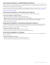
Wiring a GPSMAP 700 Series Chartplotter to a Standard NMEA 0183 Device
+
-
>
>
>
>
Red (power)
Black (ground)
Brown (in)
Blue (out)
Wire color
Power
Power ground
NMEA Ground
NMEA Rx/A (+)
NMEA Tx/A (+)
NMEA 0183-compatible
device
GPSMAP 700
series
chartplotter
Battery
10–32 Vdc
Fuse
3 A
Wire function
To connect the power/data cable to a NMEA 0183 device:
1. For Garmin devices, the ground (black) wires serve as NMEA 0183 ground and must be attached together or on the same terminal as the
NMEA 0183 ground on your NMEA 0183 device. Refer to the wiring diagram of your NMEA 0183 device for wire identication.
2. Connect the blue (NMEA 0183 port 1 out) wire from the GPSMAP 700 power/data cable to the NMEA 0183 in (or Rx/A +) wire from the
NMEA 0183 device, and the brown (NMEA 0183 port 1 in) wire to the NMEA out (or Tx/A +) wire from the NMEA 0183 device.
3. Repeat step 2 using the gray (NMEA 0183 port 2 out) and violet (NMEA 0183 port 2 in) wires for an additional NMEA 0183 device.
4. Set the serial port (or ports) on the chartplotter to use NMEA 0183 data (standard or high-speed). See the GPSMAP 700 Series Owner’s
Manual for more information.
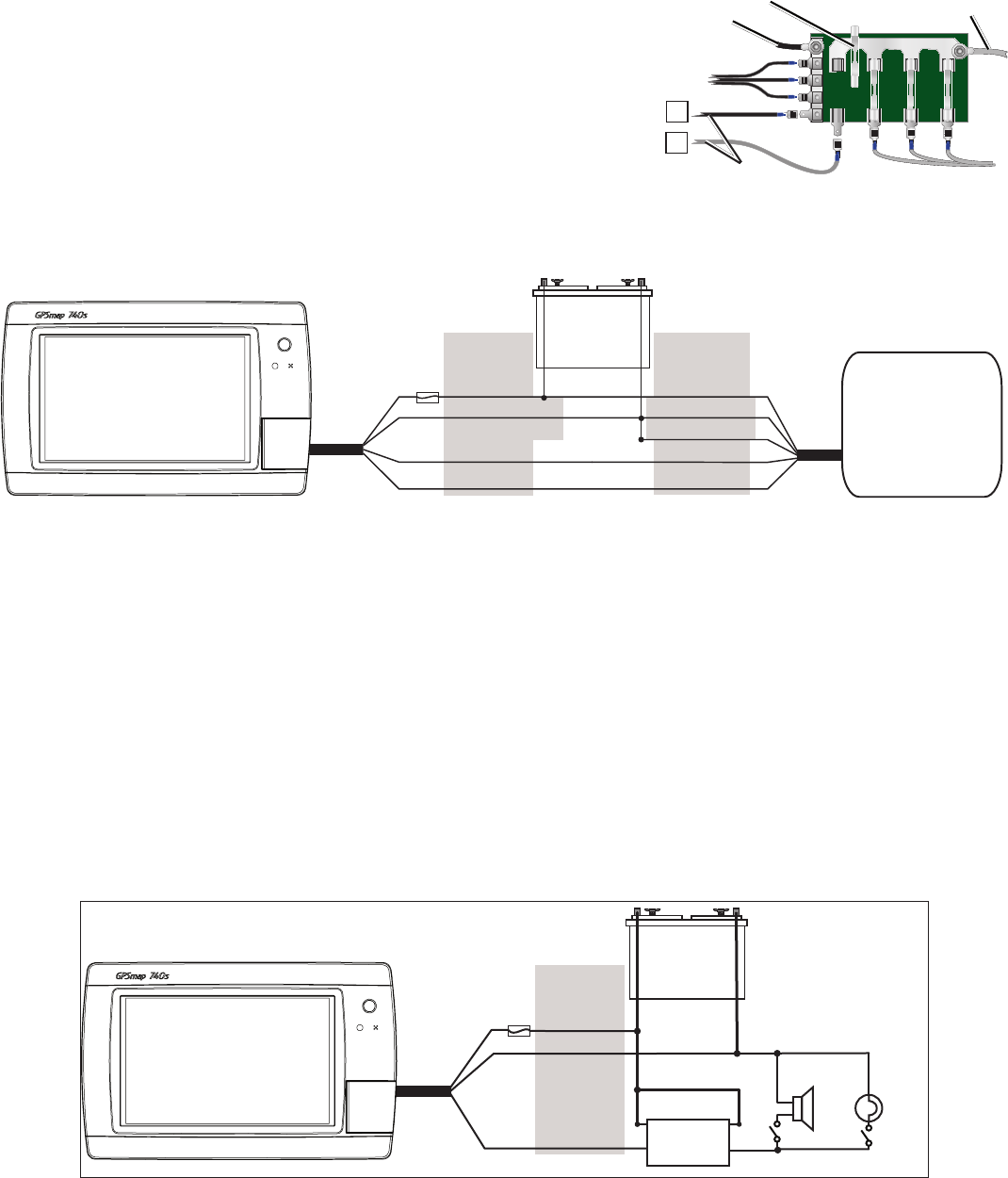
Connecting the Power/Data Cable to a Lamp or to a Horn (Optional)
The GPSMAP 700 series chartplotter can be used with a lamp, a horn, or both, to sound or ash an alert when the chartplotter displays a
message. The alarm does not need to be wired for the chartplotter to function. The alarm circuit switches to a low-voltage state when the alarm
sounds. The maximum current is 100 mA, and a relay is needed to limit the current from the chartplotter to 100 mA. To manually toggle visual
and audible alerts, install single-pole, single-throw switches.
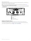
Wiring to a Lamp, a Horn, or Both
+
-
GPSMAP 700 series
chartplotter
Wire
Color
Red (power)
Black (gnd)
Yellow (alarm)
Battery
10–35 Vdc
Relay
100 ma max
coil current
Horn
Lamp
Fuse
3 A
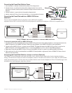
Fuse Block Example
—
+
2A
3A
-
+
Boat ground
3 A fuse
To 10–32 Vdc boat supply
To device
Fuse Block Example
—
+
2A
3A
-
+
Boat ground
3 A fuse
To 10–32 Vdc boat supply
To device