


GPSMAP 400/500 Series Installation Instructions 3
Installing a Transducer
Consult the chartplotter feature matrix on page 1 to determine if your chartplotter is capable of using sonar. The following transducer
installation procedures are only applicable to sonar-capable chartplotters.
: The following procedures contain installation instructions for the transducer included with the “s” model GPSMAP 400/500 series
chartplotters. If you choose to use a different transducer, installation instructions are provided in the transducer kits. Some transducers might
have to be installed by a professional marine installer.
Proper transducer installation is key to getting the best performance from your sonar-capable chartplotter. Be sure you have the following
components in the transducer package, as well as the following tools:
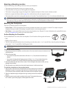
Transducer Package
• Transom-mounttransducer(notpictured)
A –5mmatwashers(2)
B –530mmscrews(2)
C –10-32locknut(1)
D –412mmscrew(4)
E –10-321.75in.screw(1)
F –
1
/
4
in.cableclamps(2)
G –Plasticspacer(1)
H –
1
/
4
in.rubberwasher(1)
I –Cabletie,5.6in.(4)
J –Cableentrycover(1)
F
H
C
D
I
J
G
E
A
B
Tools Needed
• Drillanddrillbits
•
3
/
8
in.(9.5mm)wrenchorsocket
• Maskingtape
• Number2Phillipsscrewdriver
• Marinesealant
Do not cut the transducer lead or any part of the transducer cable. Cutting the transducer cable voids your warranty. The cable cannot be
spliced and connected to any existing (Garmin or non-Garmin) transducer cables. If the transducer lead is too short, extension cables are available from
your Garmin dealer.
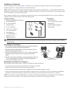
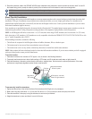
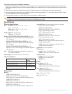
Assembling the Transducer
1.Inserttherubberwasher(H)andtheplasticspacer(G)intothetransducer
atthesametime.DONOTlubricatetherubberwasher.
2. Routethepower/datacabletowardthebackofthetransducer.Slidethe
transducerintothetransducermount.
3.Placea5mmatwasher(A)onthe10-32×1.75in.screw(E),andinsert
thescrewthroughthetransducermount,thespacer,andtherubber
washer.
4.Placetheremaining5mmatwasher(A)ontheexposedendofthe10-32
×1.75in.screw.Installthe10-32locknut(C)ngertight.Retightenthe
transducerafterinstallationontheboat.
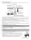
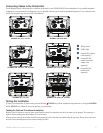
Mounting the Transducer on a Transom
When selecting a transom-mount location, consider the following for optimal performance:
• For your sonar to operate properly, the transducer must be located in calm water.
• Mount the transducer as close to the center of the boat as possible.
• Do not mount the transducer in locations where it might be jarred when launching, hauling, or storing.
• Do not mount the transducer in the path of the propeller on single-drive boats. The transducer can cause cavitation that can degrade the
performance of the boat and damage the propeller. On twin-drive boats, mount the transducer between the drives, if possible.
Do not mount the transducer behind strakes, struts, ttings, water intake or discharge ports, or anything that creates air bubbles or
causes the water to become turbulent. The transducer must be in clean (non-turbulent) water for optimal performance.
Back of the transducer
Cable tie slot
E
G
H
A
C