


4 GPSMAP 400/500 Series Installation Instructions
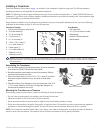
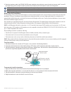
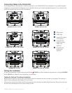
To mount the transducer on a transom:
1. Positionthetransducermountattheselectedtransomlocation.Makesurethetransducerisparallelwiththewaterline.Markthecenter
locationsofeachholeonthetransducermount.
Apply marine sealant to all screw
threads to prevent water from
seeping into the transom.
Mount the transducer
cable cover far above
the waterline.
The transducer should
extend
1
/
8
in. (3.2 mm)
below a berglass hull or
3
/
8
in. (9.5 mm) below an
aluminum hull.
Ensure that the transducer is
below water level when the boat
is on plane at high speed.
Do not mount the transducer directly in the path of the
propeller. The transducer can cause cavitation that may
degrade the boat performance and damage the propeller.
Mount the transducer parallel
with the bottom.
2. Drill
5
/
32
in.(4mm)pilotholesapproximately1in.(25mm)deepatthemarkedlocations.Toavoiddrillingtheholestoodeep,wrapapieceof
tapearoundthebitat1in.(25mm)fromthepointofthebit.
3. Applymarinesealanttothe5×30mmscrews(B).Attachthetransducerassemblytothetransomusingthe5×30mmscrews.Adjustthe
transducerassemblytoextendbeyondthebottomofthetransomapproximately
1
/
8
in.(3.2mm)onberglasshullsor
3
/
8
in.(9.5mm)on
aluminumhulls.Adjustthetransducerassemblytobealignedparallelwiththebottom.
4. Tightenthe10-32lockingnutuntilittouchesthemountingbracket,andthentighten
1
/
4
turnmore.(Donotovertighten.)
5.Placetherstcableclamp(F)onthetransducercable,approximatelyonethirdofthedistancebetweenthetransducerandthetopofthe
transom.
6. Markthelocation.Drilla
1
/
8
in.(3.2mm)pilotholeapproximately
3
/
8
in.(9.5mm)deep.
7.Attachthecableclampusingoneofthe4×12mmscrews(D).Coatthescrewwithmarinesealantbeforeinstallation.Repeatsteps5and6
usingtheothercableclamp.
8. RoutethetransducercabletotheGPSMAP400/500serieschartplotter.
Avoid routing the cable close to electrical wires or other sources of electrical interference.
9. TestthetransducerinstallationafteryoucompletetheGPSMAP400/500serieschartplotterinstallation.Seepage9.
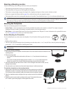
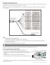
Mounting a Transducer on a Trolling Motor
1.Withtheridgesofthebandfacingup,slidethelargecabletiethroughtheslotonthetransducermountuntilequallengthsextendonboth
sidesofthemount.
For cold water and heavy timber or debris areas, a metal 4-5 in. (100-125 mm) worm gear clamp is recommended instead of the plastic
cable tie.
2. Positionthemountgasketonthecurvedtopofthetransducermount.
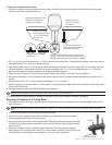
3.Withthefrontofthetransducerpointedawayfromthetrollingmotorpropeller,placethetransducer
assemblyagainstthemotorbodyofthetrollingmotor.
4.Wrapthetwoendsofthecabletiearoundthemotorbody.Placethepointedendofthecabletiethrough
thefastenerholeontheoppositeendandpullitthroughuntilitissnugbutnottight.(Thecabletieclicks
whenyoupullit.)
5. Positionthetransducersothatitisparallelwiththebottomwheninuse,makingsurethegasketis
alignedproperly.Pullthecabletieenduntiltight.Trimofftheexcessifnecessary.Tightenthelockingnut
untilittouchesthemountingbracket,andthentighten
1
/
4
turnmore.(Donotovertighten.)
Cable tie
Front of the transducer