


Av. Kit Install. Manual
190-00067-02 Rev. J
Page 19
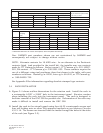
Identification data
Label
(octal) Description
377 Equipment identifier
371* General Aviation equipment identifier
*These labels are formatted per the General Aviation Manufacturers Association
(GAMA) definition. Note that the use of a 429 device w/o GAMA will cause the loss
of the above asterisked labels. Some may be required for A1 certification. For
example, label 326 changes the CDI scale for approach.
4.2.5 CDI CALIBRATION
Select the test page displaying CDI output calibration. Place the cursor on the
alignment field by using the outer knob. Use the inner knob to adjust the CDI needle
until it is centered. Once centered, turn the cursor off to complete the calibration
process.
4.2.6 SELECTED COURSE CALIBRATION
Select the test page displaying the selected course input. Using an extremely accurate
input source, input 150° to the GNC 300. The input course will indicate close to 150
and a Calib? field will appear in the lower right corner. Selecting the Calib? field
will calibrate the GNC 300 to match the input source. Verify OBS operation by
checking that the bearing displayed on the GNC 300 is within 2° of the selected
bearing. Do this for every multiple of 30° around the OBS.
4.2.7 APPROACH SETTINGS
Select the Approach Settings Test Page. Move the cursor over the approach switch
field to change the installation state.
The available options are:
Appr switch: Field Description
none The approach switch is not present
instld The approach switch is installed
NOTE: To verify the installation of the approach switch, the instld
setting requires the approach switch to be pressed to confirm its
presence. The following prompt is displayed in this case: press appr
switch to confirm along with a ? following instld. When the switch
press is recognized the prompts are cleared and the instld setting is
confirmed.