


4 VHF 300 Series Installation Instructions
* A
1
/
8
in. (3 mm) pilot hole is nominal for plywood. Different dashboard materials my require a different size pilot hole.
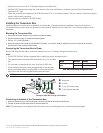
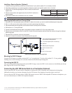
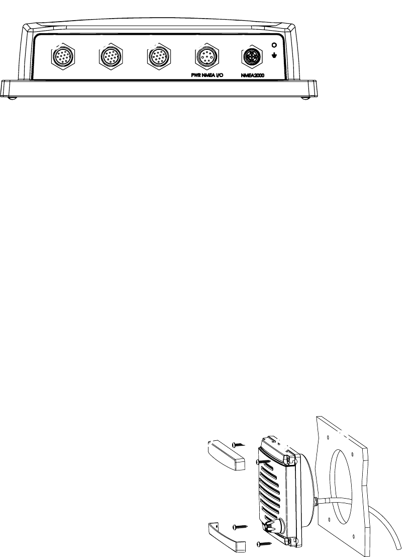
Identifying the VHF 300 Transceiver Box Connectors
Use the illustration to identify the connectors on the VHF 300 transceiver box.
➊
GHS 10 expansion connector
➋
HS-1—primary GHS 10 connector
the wheelhouse GHS 10 must connect to
this port
➌
VHF 300 power/data cable connector
➍
NMEA 2000 connector (optional)
Antenna port (on back - not pictured)
➊ ➋ ➌➊ ➍
VHF 300 Transceiver Box Connectors
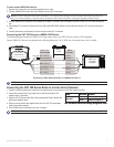
Installing the GHS 10 and Speaker
The GHS 10 connects to the transceiver box and to either the Garmin GHS 10 active speaker (included) or a passive speaker (not included).
When planning the GHS 10 installation, consider the following:
Per FCC law, you must install the GHS 10 in the wheelhouse or an adjacent room.
Install the GHS 10 and the active speaker at least 20 in. (.5 m) from any compass.
Install the active speaker within 48 in. (1.2 m) of the location you mount the bulkhead pass-through plate.
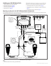
Consult the VHF 300 Series Layout Diagram on page 2 to determine how to connect the GHS 10 through a bulkhead to a speaker and to the
transceiver box.
If the cable is not long enough to reach the GHS 10 mounting location from the transceiver box, extension cables are available in lengths of
16 ft. (5 m) and 32 ft. (10 m). Install any extensions between the GHS 10 cable and the transceiver box according to the layout diagram on
page 2.
When you install the GHS 10 active speaker, if you use the GHS 10 cable to connect the active speaker to the transceiver box, do not
connect a passive speaker to the GHS 10 cable. Clip and tape the passive speaker wires.
Installing the GHS 10 Active Speaker
1. Use the GHS 10 active speaker Flush Mount Template to mount the active speaker. The template is self-adhesive.
2. Remove the paper backing from the template and adhere it to the bulkhead in a suitable location.
3. Use a 3
1
/
2
in. (90 mm) hole saw to cut the opening as indicated on the template.
4. Place the speaker in the cutout.
5. Ensure that the mounting screw locations align with
the holes marked on the template. If they do not,
mark the locations of new pilot holes.
6. Drill four
1
/
8
in. (3 mm) pilot holes* in the correct
location.
7. Use the included M4.2×25 screws to mount the
active speaker.
8. Snap the cover plates on the active speaker.
9. To install the active speaker wiring harness to the
transceiver box, use the GHC 10 cable according to
the layout diagram on page 2.
Do not connect a passive speaker to the GHC 10
cable you use with the active speaker. Clip and tape the two passive speaker wires.
If the GHC 10 cable is not long enough to reach the transceiver box location, install an extension (not included) between the GHC 10
cable and the transceiver box as shown on the layout diagram on page 2.
10. To install the active speaker wiring harness though the bulkhead, follow the procedures on page 5.
•
•
•
•
•
•
•
•
➊
➋
➌
➍
➊
Cover plates (×2)
➋
M4.2×25 screws (×4)
➌
Active speaker
➍
Bulkhead
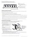
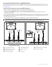
Mounting the Active Speaker
➊
➋
➌
➍
➊
Cover plates (×2)
➋
M4.2×25 screws (×4)
➌
Active speaker
➍
Bulkhead
Mounting the Active Speaker