


VHF 300 Series Installation Instructions 5
* A
1
/
8
in. (3 mm) pilot hole is nominal for plywood. Different dashboard materials my require a different size pilot hole.
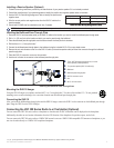
Installing a Passive Speaker (Optional)
1. Follow the mounting instructions provided by the manufacturer of your passive speaker if it is not already mounted.
2. Consult the manufacturer of your passive speaker to identify the positive and negative speaker wires or terminals.
3. Use the GHS 10 Cable Wiring-Assignment Table to identify the positive and
negative wires.
4. Wire the correct positive and negative wires from the GHS 10 cable to the
passive speaker.
5. Use at least 22 AWG wire for extended runs of wire, if needed.
NOTICE: Cover the connections with a waterproof, adhesive tape, such as rubber vulcanizing tape, to prevent water from seeping into the radio.
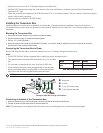
Installing the Bulkhead Pass-Through Plate
1. Route the GHS 10 active speaker cable (or the GHS 10 cable) to the location you want to install the bulkhead pass-through plate.
2. Drill a 1 in. (25 mm) hole in the location at which you want to pass through the bulkhead.
3. Place the bulkhead pass-through plate over the hole and mark the three pilot-hole locations.
4. Drill the three
1
/
8
in. (3 mm) pilot holes.*
5. Connect the bulkhead pass-through plate to the bulkhead using the included M3.5 × 20 mm pan-head screws.
6. Remove the nut and connector cover from the GHS 10 cable (or the active speaker cable) and feed the connector through the bulkhead
pass-through plate.
7. Place the GHS 10 connector cover over the connector.
8. Use the nut to fasten the connector to the bulkhead pass-through plate.
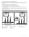
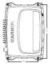
Installing the Bulkhead Pass-Through Plate
➊
To the VHF 300 series transceiver box, or to the
active speaker (cable dependent)
➋
To a passive speaker (GHS 10 cable only)
➌
Bulkhead
➍
Bulkhead pass-through plate
➎
GHS 10 connector cover
➏
Nut
➐
M3.5 × 20 mm screws
➊
➋
➌
➍
➎
➏
➐
Mounting the GHS 10 Hanger
Using the GHS 10 hanger as a template, mark and drill
1
/
8
in. (3 mm) pilot holes.* Use three of the included 3.5 × 20 mm, panhead
mounting screws to mount the hanger in a convenient location near the bulkhead pass-through plate.
Connecting the GHS 10
After you install the bulkhead pass-through plate and the GHS 10 hanger, connect the GHS 10 to the connector on the bulkhead pass through
plate. Hang the GHS 10 on the GHS 10 hanger.
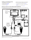
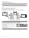
Connecting the VHF 300 Series Radio to a Chartplotter (Optional)
You can connect the VHF 300 series radio to a chartplotter so that data such as DSC information can be displayed on the chartplotter.
Additionally, the radio can use location information from the GPS function of the chartplotter for position reports, and so forth.
You can connect the VHF 300 series radio to a NMEA 2000 network to access a NMEA 2000-compatible GPS antenna or chartplotter, or you
can wire the radio directly to a NMEA 0183-compliant chartplotter.
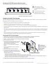
Device Wire Color Function
GHS 10 cable Yellow Speaker positive (+)
Green Speaker negative (-)
GHS 10 Cable Wiring-Assignment Table
Device Wire Color Function
GHS 10 cable Yellow Speaker positive (+)
Green Speaker negative (-)
GHS 10 Cable Wiring-Assignment Table