


VHF 300 Series Installation Instructions 7
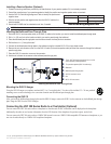
To create a basic NMEA 2000 network:
1. Connect two T-connectors (not included) together by their sides.
2. Connect a NMEA 2000 power cable (not included) to one of the T-connectors.
NOTICE: A NMEA 2000 power cable must be connected to a 12 Vdc power source through a switch. The NMEA 2000 network may drain your
battery if it is connected directly. Connect the cable to the ignition switch of the boat if possible, or through an appropriate additional switch.
3. Connect a NMEA 2000 drop cable (not included) to the other T-connector and to the NMEA 2000 port on the VHF 300 Series transceiver
box.
4. Add additional T-connectors for each device you add to the NMEA 2000 network, and connect each device to a T-connector with a drop
cable.
5. Connect terminators (not included) to each end of the combined T-connectors.
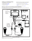
Connecting the VHF 300 Series to a NMEA 0183 Device
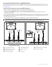
The following diagram illustrates the NMEA 0183 wiring used to connect your VHF 300 series radio to a GPS chartplotter.
Connect NMEA 0183 bare wires as indicated in the following illustration. Use 22 AWG wire for extended runs of wire, if needed.
+
-
>
>
>
>
>
>
>
>
NMEA 0183-
compatible
chartplotter
VHF 300
transceiver box
Battery
12 Vdc
White—Rx A (+)
Orange/White—Rx B (-)
Gray—Tx A (+)
Pink—Tx B (-)
Red—power (+)
Black—ground (-)
Tx A (+)
Tx B (-)
Rx A (+)
Rx B (-)
Power +
Ground -
Wire Color
and Function
Wire
Function
Fuse 10A
Connecting a VHF 300 Series Radio to a NMEA 0183 Device
NOTICE: Cover the connections with a waterproof, adhesive tape, such as rubber vulcanizing tape, to prevent water from seeping into the radio.
Connecting the VHF 300 Series Radio to a Hailer Horn (Optional)
1. Follow the mounting instructions provided by the manufacturer of your hailer horn if it is not already mounted.
2. Consult the manufacturer of your hailer horn to identify the positive and
negative wires or terminals.
3. Use the VHF 300 Series Hailer-Horn Wiring Assignment Table to identify the
positive and negative wires.
4. Wire the correct positive and negative wires from the VHF 300 power/data
cable to the passive speaker.
5. Use 22 AWG wire for extended runs of wire, if needed.
NOTICE: Cover the connections with a waterproof, adhesive tape, such as rubber vulcanizing tape, to prevent water from seeping into the radio.
Cable Wire Color Function
VHF 300 power/
data cable
Yellow Hailer-horn positive (+)
Green Hailer-horn negative (-)
VHF 300 Series Hailer-Horn Wiring-Assignment Table
Cable Wire Color Function
VHF 300 power/
data cable
Yellow Hailer-horn positive (+)
Green Hailer-horn negative (-)
VHF 300 Series Hailer-Horn Wiring-Assignment Table