


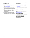
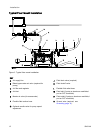
Installation
Fluid Supply L
ine
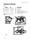
See Typical Floor Mount Installation, page 12
1. Use grounded fl
exible, fluid supply hoses (G).
See Groundin
g, page 8 .
2. If the inlet fl
uidpressuretothepumpismore
than 25% of th
e outlet working pressure, the ball
check valves
will not close fast enough, resulting
in inefficie
nt pump operation.
3. Excessive i
nlet fluid pressure also will shorten
diaphragm l
ife. Approximately 3 - 5 psi (0.02-
0.03 MPa, 0
.21-0.34 bar) should be adequate
for most ma
terials.
4. For maximu
m suction lift (wet and dry), see
Technical
Data, page 20. For best results,
always ins
tall the pump as close as possible to
the mater
ial source.
Fluid Outlet L
ine
See Typical Floor Mount Installation, page 12.
1. Use grounded,
flexible fluid hoses (L). See
Grounding, p
age 8 .
2. Install a flui
d drain valve (J) near the fluid outlet.
3. Install a shu
toff valve (K) in the fluid outlet line.
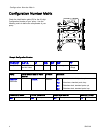
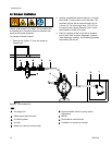
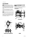
Fluid Inlet and Outlet Ports
NOTE: Remo
ve and reverse the manifold(s) to
change the
orientation of inlet or outlet port(s). Follow
Torque Ins
tructions, page 16.
1050HP — Aluminum Manifolds
The fluid inlet and outlet manifolds each have two 1
in. npt(f) or bspt threaded ports (M, N). Close off the
unused port using the supplied plugs.
1050HP —
Stainless Steel Manifolds
The fluid inlet and outlet manifolds each have one
1 in. npt(f) or bspt port.
334014A
11