


Installation
•
Air and fluid hoses:
Use only grounded hoses
with a maximum of 500 ft (150 m) combined hose
length to ensure grounding continuity.
•
Air compressor:
Follow manufacturer’s
recommendations.
•
Fluid supply container:
Follow your local code.
•
Solvent pails used when flushing:
Follow your
local code. Use only conductive metal pails
placed on a grounded surface. Do not place the
pail on a nonconductive surface, such as paper
or cardboard, which interrupts the grounding
continuity
Check your s
ystem electrical continuity after the
initial in
stallation, and then set up a regular schedule
for checki
ng continuity to be sure proper grounding
is maintai
ned.
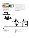
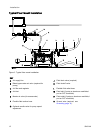
Air Line
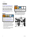
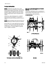
See Typic
al Floor Mount Installation, page 12
1. Install an air filter/regulator (C). An air line filter
removes harmful dirt and moisture from the
compressed air supply. Use the regulator and
gauge to control the fluid pressure. The fluid stall
pressure will be the same as the setting of the
air regulator.
2. Locate a bleed-type master air valve (B) close to
the pump and use it to relieve trapped air. Be
sure the valve is easily accessible from the pump
and located downstream from the regulator.
Trapped air c
an cause the pump to cycle
unexpectedl
y, which could result in serious
injury from
splashing.
3. Locate another master air valve (E) upstream
from all air line accessories and use it to isolate
them during cleaning and repair.
4. An adjustable inlet air valve or needle valve (G)
my be installed for pump speed control.
5. Install a grounded, flexible air hose (A) between
the accessories and the 3/4 npt(f) pump air inlet
(D). Use a minimum 5/8 in. (16 mm) ID air hose.
334014A 9