


General Information
14 3A1163A
General Information
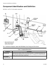
• Reference numbers and letters in parentheses in
the text refer to numbers and letters in the illustra-
tions.
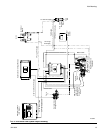
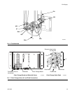
•F
IG. 2 on page 10 shows the basic components of a
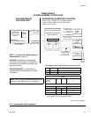
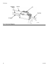
ProControl 1KS system, and F
IG. 4 on page 15
shows a basic system layout. Contact your Graco
distributor for an actual system design.
• Be sure all accessories are adequately sized and
pressure-rated to meet system requirements.
• There must be a shutoff valve between each fluid
supply line and the ProMix system.
• A 100 mesh minimum fluid filter must be installed on
component A fluid supply line.
• To protect the EasyKey screens from paints and sol-
vents, clear-plastic protective shields are available
in packs of 10 (Part No. 197902). Clean the screens
with a dry cloth if necessary.
Wall Mounting
1. See Dimensions and Mounting Hole Layouts,
page 32.
2. Ensure that the wall and mounting hardware are
strong enough to support the weight of the equip-
ment, fluid, hoses, and stress caused during opera-
tion.
3. Using the equipment as a template, mark the
mounting holes on the wall at a convenient height
for the operator and so equipment is easily accessi-
ble for maintenance.
4. Drill mounting holes in the wall. Install anchors as
needed.
5. Bolt equipment securely.